Instructions for safe removal of calender stack rolls and drives
Aug 23, 2016
Safety reminders

 |
DANGER: Falling rolls or tools could result in death or severe injury. All personnel involved in the roll removal process or working in the vicinity of the calender should read the mill's and OEM's safety precautions and procedures before removing rolls from the calender. |

Due to the weight of the rolls and their overall size, accidents while handling rolls can cause serious injury or death to personnel, and costly repairs to the roll itself. However, calender rolls can be safely installed or removed if basic safety rules are followed.
Cool down all heated equipment in the vicinity of the roll to be changed or equipment being worked on. This includes rolls which become heated by contact with the web.
- Adjust the temperature of the water or oil circulating throughout any roll heating unit and its circuit to approximately 40°C (104°F). Allow the stack to cool down to this level at reduced speed and stack loading.

 |
DANGER: To avoid severe burns, cool circulating heating medium to 40°C (104°F) and shut off the heating units before beginning thermo roll changes. Follow the recommended procedures. Even after "cooling", be cautious of draining water or oil; it is still hot. |

- Cool down any heated roll doctors.
- Cool down any steam showers.
Never re-torque bolted on journals on any iron rolls.

 |
WARNING: Do not re-torque bolted-on journals on any iron rolls. These bolts are torqued to factory specifications with the roll at a specified temperature. Additional tightening or any adjustment to the bolts could cause over-stressing of the bolts with possible bolt failure, which may result in equipment damage and/or personal injury. |

Make sure to correctly re-connect rotary union hydraulics.
Roll removal instructions
Overview
Machine calender rolls are typically removed using a house crane and slings.
The following are typical stack roll removal instructions. Refer to original equipment supplier documentation and mill procedures for the actual procedures.
Removing a Stack Roll
1. Open the stack.
2. Shut down everything in the lead-in, stack and lead-out sections.
3. Retract any equipment which would impede roll removal and which requires electrical, hydraulic or pneumatic connections.
4. Lockout all electrical, hydraulic and pneumatic connections in the lead-in, stack and lead-out sections.
5. Remove any auxiliary equipment such as doctors, nip guards, threading equipment, drive shaft, etc. which would impede roll removal.
6. Wrap the slings around the top roll and place the slings on the house crane. Remove any slack from the slings, but do not lift the roll yet.

 |
CAUTION: Only tighten the slings, DO NOT lift the roll. |

7. When changing the bottom roll, shut off and disconnect all the top roll hydraulic connections and wipe off any oil collecting on the roll.
8. When changing the top roll, use an anti-rotation device to prevent unexpected rotation of the bearing housings.

 |
WARNING: The bearing housings are heavier on the side near the frame. They will rotate when free and must be restrained. |


 |
NOTE: The top roll bearing housings may have a threaded hole which is intended to be used with an eyebolt or similar component to assist in fastening a come-along during crane roll transfers. This is recommended to prevent unexpected roll rotation. |

9. Loosen the mounting bolts on the bearing housings of the roll being removed.

 |
DANGER: Do not loosen the mounting bolts unless the lifting equipment is securely in place. |

10. Remove the expanding key from the keyway (one TS, one DS).
11. Remove the mounting bolts from the bearing housings of the roll being removed.
- First remove the bottom bolts (on both the TS and the DS), then remove the top bolts. The roll is now supported fully by the angled lip or hanger bar and the slings.
12. Lift the roll out of the stack using the house crane.

 |
WARNING: Make sure to position the house crane in exact alignment with the roll, both length and width, to prevent contact with other equipment during roll removal. Do not lift rolls any higher than necessary. Use the slower crane lifting speed. The faster speed should be reserved for raising and lowering empty crane hooks. Do not carry rolls over personnel. |

13. Replace the rolls in reverse order and re-assemble all equipment by reversing the above directions.

 |
NOTE: When replacing the top roll, make sure to use an anti-rotation device to prevent the roll's dead shaft from rotating in the bearing housings. |


 |
NOTE: When replacing the bottom roll, make sure to: grease the spherical plain bearings in the bottom roll's bearing housings, re-assemble the appropriate bottom roll hydraulics and position the pressure side of the bottom roll to face upward. |

Removing drives from stack rolls

 |
DANGER: Before disconnecting the drives, make sure to: shut down everything in the lead-in, stack and lead-out sections; lockout all electrical, hydraulic and pneumatic connections in the lead-in, stack and lead-out sections; thoroughly cool all heated equipment in the vicinity of the drive, especially any thermo rolls; and before removing a drive from a thermo roll, drain the roll. |

Disconnect the drive shaft from driven stack rolls as follows:
1. Remove the section of the drive shaft guard closest to the roll. Where applicable, also remove any belt drive guard.
2. Support the universal drive shaft using a portable lifting device such as a chain fall. (Do not allow the weight of the universal drive shaft to rest on the guard.)
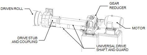
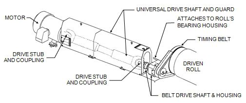
3. Depending on the drive design, either unfasten the universal drive shaft from the roll journal's drive hub (Figure 1), or from the belt drive shaft and housing (Figure 2).
4. Where applicable, unbolt the belt drive eccentric housing from the roll’s bearing housing (Figure 2).

Figure 1 Typical drive assembly for a fixed position roll

Figure 2 Combination universal drive shaft and belt drive assembly
For more information on improving safety at the calender, consult your mill's safety manager or contact your Valmet representative for training or safety rebuild options.