SIL 3 – am I safe now?
There are different aspects to think about and evaluate in the case of a safety valve.
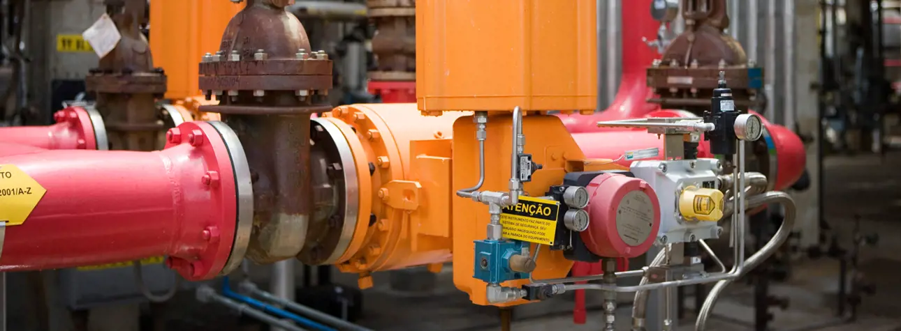
ESD valve
An emergency shutdown (ESD) valve is part of a safety instrumented system (SIS). It is a vital part of the safety system and often described as the final element. Normally, the term ESD valve refers to all types of safety system valves, such as shutdown, emergency shutdown, emergency ventilation or blowdown valves. There is much confusion in the functional safety area when it comes to what should be considered with regards to safety valves to make a plant safe. There are different aspects to think about and evaluate in the case of a safety valve. Excellent probability of failure on demand (PFD) and safety integrity level (SIL) are just two examples.
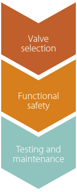
There is much more than the SIL certification that is needed. For ESD valves, there are three main steps.
Valve selection
The most important step in the selection of an ESD valve is to use the application-based valve selection process. This step has not been observed often enough in recent years, while the functional safety calculations have attracted excessive attention.
ESD valves have the same application challenges as normal on-off valves. Correct valve selection includes valve type, pressure class, temperature, materials and other details. If the selection does not fit the application in question, valve failure will be systematic, and we cannot take advantage of the functional safety calculations of the SIL and PFD value. Systematic error in valve selection will make the valve fail every time in the same way, and random error rate will no longer be the main source of failure.
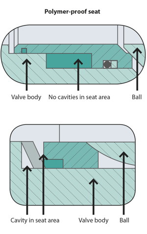
A very good example of systematic error is incorrect seat selection. We can use the example of polymer service to demonstrate systematic error. There are a number of different types of valves and seats in the market, but only some of them can be used in polymer service. After we know the correct pressure class, materials and temperature range, we must consider other details to make the valve work in a real process. A rough categorization could include seat types that have contact between the sealing elements all along the stroke and seat types that lose the contact while operating like plug and rising stem valves. The problem with seat types that lose contact is the polymer accumulation between the surfaces. The valve does not fully work or starts to jam after that. This problem can be solved by selecting a rotary ball-type valve with a scraping seat that wipes the sealing surface clean while stroking the valve. This solves one problem, but after selecting the ball-type valve, there are still multiple different seats. The so-called open-seat design (Figure 2) will get jammed when the polymer enters the seat cavity. This problem can be solved by using a closed-seat design in which the functional feature of the seat is protected. This type of seat is an excellent choice for processes that have impurities. For the ESD valve, it would be a disaster if the valve seat is jammed when the valve needs to operate.

Functional safety – take full advantage
The previous example highlights the importance of application-based valve selection. Even for an incorrect seat type, it would be possible to calculate a high SIL and a good PFD value. If we look at the PFD value alone, it cannot guarantee plant safety.
Following the international standard IEC 61508 and 61511, we typically have a safety integrity level to match based on the hazard and operability analysis (Hazop) and safety integrity level assessment. The final elements are a critical part of the safety loop. If devices, such as valves, are not working properly, the safety instrumented function is not available. In recent years, there have been a number of announcements of manufacturers publishing SIL certification and advertising SIL 3 valves. The certification proves that the valve is capable of working in an SIL 3 loop, but it does not guarantee that the function is SIL 3. The final element is part of the safety loop, and, therefore, component certificates are not enough to assure the safety integrity level of the loop. The complete final element as an assembly must be calculated, taking into account all components that are needed for the safety function.
In the final element assembly, typical components are the valve body, actuator and intelligent safety solenoid. All these components have their own component SIL certification and PFD value, which can be calculated according to the testing intervals.
From the example, it is easy to notice the effect of the testing intervals. Even if the SIL 2 capability is achieved in both examples, the PFD value will change. Only by calculating the complete system is it possible to know the final safety system capability.
Testing & maintenance
Service and testing make up a large part of the ESD valve’s life cycle. ESD valves should not be so-called “install and forget” devices. The only way to maintain the safety integrity is to have a test plan and to follow that plan. In the example above, the testing interval for full stroke testing was 48 or 36 months; for partial stroke testing, it was 3 months. If the testing according to plan is not done, the safety integrity level is not maintained. Using the Nelprof™ SIL tool, it is also easy to see what the testing intervals should be as well as what the effect will be on the PFD value if the testing is not possible at that interval. A partial stroke test (PST) interval of one to three months is typically done with an intelligent safety solenoid, such as Neles™ ValvGuard™, to automate the testing routine and documentation.
ESD valve testing is typically categorized into two different types. A partial stroke test (PST) can be done while the plant is operating, and a proof test happens during shutdowns. The difference between the testing types is that the full stroke of a valve in a proof test will impact the operation of the plant, and the partial stroke test can be done without causing any harm to the process. During the PST, the valve is moved just a few percent of the full stroke to analyze its condition. In proof tests, the full stroke test will complete a 100% stroke. The advantage of carrying out the PST is that the full stroke test then does not have to be done so often and will help to match the turnaround period of the plant.
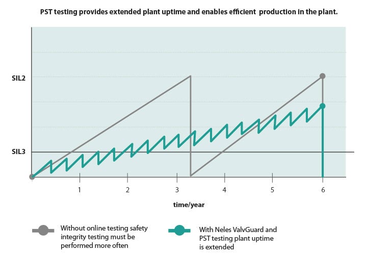
From the graph above, it is easy to see the advantage of the PST. The gray colored line reached the SIL 2 level much faster than the green colored line with PST. We can also see that it is not possible to completely avoid the proof testing by doing the PST, but the interval for the full stroke testing can be longer.
Summary
ESD valve selection involves more than just calculating the PFD and safety integrity level. The basic work of the application-based valve selection is still a very important part of the ESD valve selection process. After the valve is capable of working in the application, we can take full advantage of functional safety calculations. After these steps are completed to ensure the plant safety during the full life cycle, the testing and maintenance of the valves are important to make sure the ESD valve will work when it needs to work.
TEXT: Ville Kähkönen
PHOTOS: Erik Grönlund, Shutterstock & Valmet
Published in Results flow control customer magazine 2/2015.
Originally published in Hydrocarbon Engineering magazine, June 2015 issue, as ’Am I safe now?’
Text originally published in 2015, and slightly updated in April 2022, due to the company name change to Valmet.
Subscribe to our newsletter
Subscribe now to flow control newsletter and receive the latest insights directly to your email.
Subscribe