Solutions to severe service control valves
In this article we outline the importance of selecting the most appropriate severe service control valves. Control valves are an important part of the refining and chemical industry. The selection of these valves requires considerable understanding of the control valve sizing and selection, trim designs, materials, and a controller device.

While there are many so-called standard control valves that are part of the process, there is a certain percentage of valves that are under severe process conditions, meaning they need to be selected more carefully. The valves in these services are subject to challenging conditions that affect their performance. As a result, having knowledge of these challenges and being able to provide informed recommendations for solutions is crucial to ensuring proper functioning of the valve, which in turn leads to improved plant efficiency, life cycle maintenance costs and reliability. Typically, there are three different types of control valves: linear, rotary and axial flow control valves. Selection is based on customer requirements and recommendations based on the experiences of valve vendors. The ideal approach is to select the valve based on specific applications, rather than selecting just one type of control valve for all applications.
Cavitation and flashing: challenges in liquid flow control
Cavitation is a typical example of a valve duty that is considered to be a severe service. Cavitation is a two-phase phenomenon which occurs in certain flow conditions. At the control valve restricting the flow, the pressure of the liquid decreases rapidly. As soon as the liquid’s pressure decreases below the vapour pressure level, the liquid starts to turn into a gas, creating vapour bubbles inside the flowing liquid. Essentially, the liquid boils. However, in thiscase, it is not due to the increasing temperature, but because of the pressure dropping at the throttling valve.
What makes cavitation potentially damaging is what happens right after the valve. The pressure of the flow starts to recover downstream from the so-called ‘vena contracta’, the point of smallest diameter where flow passes. As soon as the flow pressure increases above the vapour pressure, the vapour bubbles begin to collapse. The collapse of the bubbles happens rapidly and violently, causing pressure shocks inside the process fluid. Those pressure shocks cause, at best, high noise levels, but may at worst lead to mechanical damages in the valve and the equipment in the pipeline after the valve.
On the other hand, when flashing occurs, the pressure never recovers back above the vapour pressure level, so the vapour bubbles never collapse. The gas bubbles then expand due to the recovering pressure. This leads to high low velocity, which increases the risk of damage that is reminiscent of erosion.
The key to avoiding possible damage from either cavitation or flashing lies in thorough and professional valve selection. Taking extra time over the control valve selection can potentially double the lifetime of the equipment. For example, cavitation under high pressure differencial duty, combined with corrosive or erosive flow media, may result in visible damage in days or weeks, rather than in years, for cases where the valve selection has been carried out carelessly or with incorrect/incomplete process data. All valve types, designs and styles of construction have different capabilities when handling cavitation and flashing. Cavitation prevention technology typically relies on pressure staging, which can be achieved with special anti-cavitation trims. With correct valve selection, this cavitation phenomenon can be controlled, and even completely avoided, all while preventing any damage from occurring.
Today, valve selection and sizing is carried out in valve sizing software, which can automatically recognise flow conditions where phenomena such as cavitation or flashing may take place. It is important to note that not all cavitation must be prevented. Often incipient or partial cavitation is not harmful and, with some valve types, even choked flow is not dangerous with lower pressure differences. Valve sizing and selection software, such as Valmet’s Neles Nelprof™, can automatically estimate the damage potential and guide the user towards the control valve that is most suitable for the exact process conditions.

Caption 1: Cavitation is controlled by pressure staging in Neles Q-trims™, which, on account of its self-flushing feature, is also suitable to be used with dirty flow media.
When flashing occurs, the valve selection cannot prevent the phenomena itself. If outlet pressure is smaller than the vapour pressure, flashing will occur. The ideal next step is to select valve constructions that are optimised to endure the flashing and designed to direct the flow smoothly out of the valve into the middle of the pipe after the valve. Eccentric rotary plug valves and angle globe valves are both examples of valve types that excel in flashing applications. Typically, an expander after a valve is also preferred, allowing more room for the two-phase flow.

Caption 2: The Neles Finetrol™ eccentric rotary plug valve offers a versatile rotary solution for severe service applications and excels specifically in flashing service
Erosive flow: maximising the control valve lifetime
Other typical examples of severe service valve applications are control duties with clearly erosive flow media. These are typically liquid slurries or mixtures of gases with abrasive solid particles. Wear, abrasion and corrosion damage will occur similarly, regardless of whether it is a case of liquid or gas mixes, when the medium carries abrasive particles. This can be a known feature of the application – for example, when moving heavy slurries or controlling the amount of hard catalyst fines in a cracker – but also often unwanted and unknown, for example, when sand particles appear in crude oil or in natural gas lines. Nevertheless, it is an issue that needs to be tackled. Just like cavitation damage, erosion damage can occur rapidly and repairing the inner surfaces of the valve and pipeline is typically very time-consuming and expensive –considering it is even possible.
Once again, to prevent erosion damage, the crucial step is making the correct selection. With wide openings and smooth flow channels as well as limited local flow velocity maximums, a lot can already be achieved. However, to significantly increase the lifetime of the valve, material selection is the key to success. Typical solutions include upgrading valve base materials to stronger alloys and applying hard coating at least on the trim parts of the control valve. In many cases this is not sufficient and more innovative ideas are required to keep the process running without unwanted maintenance breaks. Ceramics are not uncommon protective lining elements inside valves and offer excellent erosion resistance. Ceramics do, however, have their limitations in resistance to thermal shocks and electrical conductivity, which are crucial in demanding processes. Neles WearBlock™ (see Figure 2) bi-metal valves, which use metal matrix composite materials, offer a solution in demanding applications in which wear protection similar to ceramics needs to be combined with, for example, electric conductivity.

Caption 3: The unique metal matrix composite used in the Neles WearBlock™ has been proven to work under the fiercest operating conditions, maximizing valve’s erosion resistance.
Aerodynamic noise
Controlling flows of gaseous media is often noisy. Limiting the aerodynamic noise from the process is a standard requirement for health, safety, and environmental reasons. Noise causes direct risks for the health of the personnel running the process and may also need to be controlled carefully so that excessive noise from the process plant itself is avoided. In the worst cases, gas noise can be mechanically damaging to the process equipment. At present, a typical noise limit is still 85 dBA in working environments globally, but stricter limits are not uncommon.
Methods of aerodynamic noise abatement in control valves are often divided into two basic techniques. In source treatment, the valve internals, trim and flow path are designed to minimise the generation of excessive noise. In path treatment, the already generated noise is dampened, typically by pipeline insulation or separate silencers.
Source treatment can prevent excessive noise emitted from the process, as well as limit or even eliminate the mechanical vibrations that are potentially harmful to the sensitive process equipment. Examples of source treatment methods in control valve trims include flow division, pressure staging, controlling the shock waves and frictional flow path designs (see Figure 1). Such trims specifically developed for gas noise abatement are widely available, both for rotary and linear globe control valves.
Selecting the most suitable noise abatement valve construction and trim is a task that requires expertise. Luckily, the computerised control valve noise prediction methods following internationally recognised IEC standards has been around for decades already, and now with the newest software, it is easy to simulate and compare various solutions with just a few clicks. Selecting an optimally sized gas control valve with a suitable anti-noise trim for a particular process not only ensures the best control performance that falls within the noise limits, but also maximises solution efficiency by avoiding the use of static resistors, such as diffusers or fixed resistor plates.
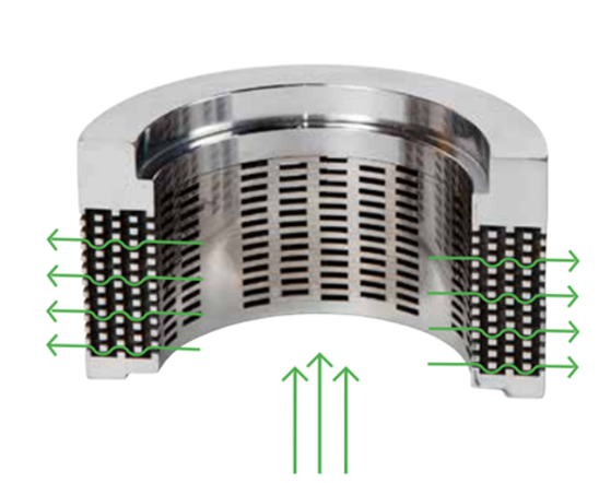
Caption 4: Neles Omega™ anti-noise trim uses flow division and pressure staging for market-leading noise abatement.
Conclusion
Putting some extra time and thought backed by experience into control valve selection can really make all the difference. Having the correct technology available and the expertise to select and size control valves for mission-critical applications and challenging process conditions enables a safe working environment for personnel and the plant. It also increases process efficiency and ensures operational availability and reliability at all times.
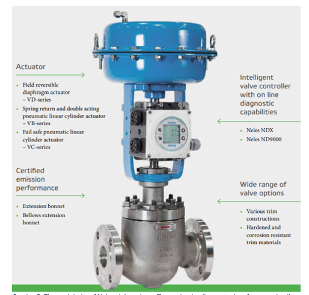
Caption 5: The modularity of Neles globe valves offer market-leading control performance in all severe service high-pressure applications.
This article was originally published in Hydrocarbon Engineering, December 2023 as ‘Careful control valve selection’.
Text by: Juha Relander
Please also check our brochure Enusuring control valve reliability - Control valve solutions for severe service

Juha Relander
Senior Manager, Control valves product line, Flow control business area, Valmet
Discover more related topics


Subscribe to our newsletter
Subscribe now to flow control newsletter and receive the latest insights directly to your email.
Subscribe