Sizer service case study – Size press inspection and repair
Jul 12, 2022

Background
A previous audit by Valmet experts had been conducted several months earlier. Recommendations from that report included adjusting the flow control valves for even size press nip loading. This had been done, but the nip continued to load faster on the tending side.
Also identified in that report was some damage to the drive side top beam turning equipment. The rod end of the cylinder had buckled the beam where the rod was connected to the beam. A search for what caused the drive side applicator beam to buckle in about 1" had come up short of identifying anything specific. The only certainty was that the buckle was caused by a severe nip loading difference front to back.
A recent report from a rod supplier also suggested that the buckle came from a severe nip loading difference condition but did not discover how the problem occurred in the first place. It was also noted that the tending side nip loading was 7 pli higher than the drive side. Once loaded, the operation of the size press was normal, according to mill personnel.
The mill called in a Valmet expert again to assist with repairs to the size press top beam. The service visit focused on repairing the drive side buckle and adding a stiffening plate to prevent it from happening again. Also, the mill wanted to identify what may have caused the beam to buckle in the first place and needed recommendations to prevent this
from occurring again.
Actions taken
Upon arrival at the mill, Valmet experts met with mill personnel. They then took measurements for a support plate patch to be welded onto the drive and tending sides of the top applicator beam. Porta-power jacks and chain-falls were used to straighten the buckle on the drive side without success (including torching the beam connection until cherry red). The support plate for the tending side was welded on without problems.
Later, while checking the hydraulic pressures around the top beam turning cylinders, the Valmet expert noticed that the pressure in the "open" side of the cylinders pegged a transmitter at over 3700 psi. Something was definitely wrong with this pressure circuit. It turned out that this backpressure on the cylinder rod end was deadlocked by a check valve in the line, so the oil had no place to go. The porta-power jack and chain-fall could not overcome this backpressure. This extraordinarily high backpressure was due to the same forces that caused the twisted beam.
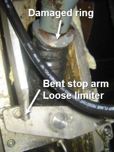
The root cause of the buckled beam was ultimately discovered to be the drive side nip loading cylinder rod. At one time, the nip load limiter bar on the drive side must have been in the down position, which allowed that side to fully retract into the roll change position. The tending side did not retract though.

This was the worst-case scenario for the beam to endure, causing the beam to buckle in on the drive side and out on the tending side. Eliminating the limiters and repairing the buckled area were required to prevent this damage from occurring again and to relieve the twisting pressure when the top beam was in the open position because this impacts nip-loading speeds. Flow control valves were adjusted to bring the TS and DS opening speeds to within 1 second of each other. Operators then rechecked top beam pre-tension.
Recommendations made
- De-commission the roll change limiters if no longer used for roll changes. Make them permanent by pinning, bolting or welding them in the up position.
- Make another attempt to push out the buckle on the drive side, this time without the 3700+ psi cylinder pressure. Alternatively, fabricate a brand new piece and put it in on a future outage.
- Load both applicator beams before closing the nip to eliminate the effect of high unloading pressure in the top beam hydraulic circuit. When the top beam loads, there doesn't appear to be any problem with wet film profiles, so the beam can't be twisted much.
- Given the information gathered during this visit, mill should hold off acting on any of the rod supplier recommendations. All three of their hydraulic recommendations were reviewed and determined to be unnecessary.
- Given that the beam may have been twisted at some time, the entire beam may need to be changed if profiles and runnability suffer.
Sizer process & condition test
The objective of a sizer process and condition test is to define the current condition of the station and to determine the service operations needed for the next scheduled shutdown or the scope of the reconditioning needs. The test also provides the mill maintenance department with useful information for their daily maintenance actions.
Contact your Valmet representative for a sizer test today.