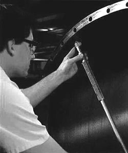
Precise head fit prevents uneven loading and excess cover wear

Many years ago, most plain press and suction rolls had straight head and shell fits and relied on an interference fit. This meant that the head was larger than the mating shell.
This interference, along with the head bolts and studs, provided the mechanical means that held the head and shell together. Over time, as these rolls are disassembled for inspection and maintenance repairs, the contact between the head and shell can wear and the head and/or shell may need to be rebuilt to restore the proper fit.
For several years now, most suction and many controlled crown (CC) rolls have been equipped with tapered head fits. Many tapered head fits have a .375 inch (9.5 mm) per foot taper on diameter cut into the shell and a duplicate taper cut into the mating head. Because the contact between the head and the shell wears over time, shim packs for the tapered head fits were developed for suction rolls to maintain a proper head fit. As the head and shell wear, shims can be removed to increase the fit.
A proper, tight head fit between the head and shell maintains roll integrity and immobilizes the roll core as the shell rotates around the core at high speed. If the fit wears beyond acceptable tolerance, it has a detrimental effect on paper quality by causing uneven loading and unnecessary roll cover wear. Avoiding the pitfalls associated with poor head fit is accomplished through regular inspections.
Inspection
Most suction rolls are disassembled every six months or once a year, while CC rolls are disassembled less frequently. Each time a roll with an interference fit is disassembled, the shell and head fits should be thoroughly inspected. These maintenance inspections provide insurance against damage caused by poor head fits.
Unfortunately, because there are few external indications of a poor head fit, the roll must be disassembled to inspect the interface. Proper inspections can detect and correct poor head fits long before external signs appear or damage occurs. A head fit inspection should include the following steps:
- Clean both head and shell surfaces.
- Ensure the head comes out straight, even and square to avoid distorting the shell bore's shape, which causes a loose fit and increases wear. Also, protect the shell and head from scratches.
- Use bluing to check the taper on the shell and head fit. Use a sine bar to ensure a minimum of 60% contact exists between the head and shell.
- If the original scribed lines are not found, scribe measuring lines on both head and shell once the head has been removed. Take four readings for an average measurement of the fit.
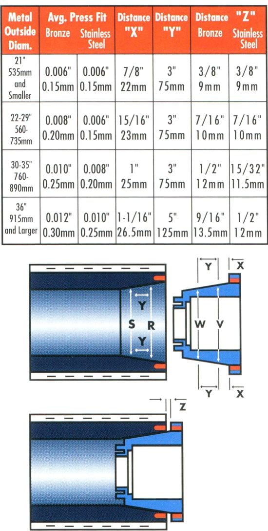
- Use the readings to calculate the press required for a proper head fit. Press, the pressure exerted between the head and shell bore, increases as the tapered head is pushed further into the shell bore. (To obtain the correct press, see the chart and caption below.)
- Calculate the amount of shims that may need to be removed or, in some cases, added to obtain the proper press.
- Ensure all high-tensile studs, used to bolt the head in place, are in good shape and have been properly torqued in the shell prior to reassembly.
- Keep accurate records of all dimensions and maintenance performed to achieve the correct head fit.

Calculating proper press. To demonstrate how to use this chart, consider a bronze roll with a 34 inch outside diameter. To calculate the interference fit, scribe a line on the inside diameter 1/2 inch from the edge of the shell to find R. To find S, measure the shell inside diameter at Y distance or 3 inches from R. To calculate head measurements, scribe the outside diameter of the head at X distance or 1 inch from the flange to find V. To find W, measure the outside diameter at Y distance or 3 inches from V. The measured diameters of W to S and V to R should be within .001 inches. For a 34 inch bronze shell, the Z distance is 1/2 inch. For a like new fit, the 1/2 inch will consist of a 3/16 inch shim pack and 5/16 inch pull in for a press fit of .010 inches.
Rebuilds
Even with proficient maintenance practices, it may be necessary to rebuild the head or shell. Eventually these components wear to the point that maintenance becomes insufficient. This happens when the maximum number of shims that allow a tight fit have been removed.
At this point, material must be added to the head to restore its original dimensions. However, because both the head and shell may wear, it may be necessary to rebuild the head larger than its original specifications. (It is easier to add material to the head than the shell.)
Three repair methods can restore the head and shell: plating, spraying and installing sleeves.
- Plating. Up to .040 to .050 inches (1.00 to 1.25 mm) on diameter can be nickel plated economically.
- Metal spraying. A thin metal coating up to .125 inches (3 mm) on diameter can be applied to the surface.
- Sleeve installation. The head is cut and a metal ring is installed.
Many mills install a sleeve to restore the necessary fit between the head and shell. However, because a sleeve can weaken the head, roll specialists recommend plating first, metal spraying second and installing sleeves third. Because sleeves are the last recourse, it is recommended that a new head be ordered once a sleeve is installed.
These three repair methods offer quick, affordable solutions to prolong head and roll life. Good roll performance will continue if maintenance inspections and appropriate repairs are made to preserve head fit.
For more information about getting the correct head fit, contact your Valmet representative.