Guest blog: Gas compressibility factor and control valve sizing
Our guest writer Jon F. Monsen on the theories behind control valves and how to apply that in reality when choosing and sizing control valves.
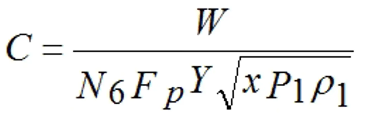
The basic gas control valve sizing equation given in ISA-75.01.01-2012 and IEC 60534-2-1 (Second Edition), when arranged so as to be solved for “C,” takes the form shown below:
C is defined as being either Cv or Kv depending on the value of N6. This equation requires a value for the upstream density of the gas where the symbol for density is ρ (rho). The equation assumes that the user knows an accurate value for the density. There are accurate tables for a few gasses, the best example being steam, but such accurate information is not readily available for most industrial gasses. The standards (actually the ISA and IEC standards are identical) make allowance for this fact by including two additional equations. These equations, one based on mass flow units (symbol W) and one on volumetric flow units at standard conditions (symbol Qs) substitute for the upstream density a calculation of density based on the ideal gas equation using the molecular weight of the gas, its upstream pressure, and upstream temperature. To correct for the fact that a calculation of the density of a gas using the ideal gas equation does not always duplicate actual behavior, the standards include the compressibility factor (symbol Z) to include the degree to which a particular gas does not follow ideal gas behavior. The standards do not make any suggestions as to how one should go about determining the compressibility factor.
Nelprof™ control valve sizing and selection software calculate the compressibility factor for any one of 49 common gasses contained in its database. This calculation is based on the van der Waals equation of state. If you do not select one of the 49 gasses in the database, the program returns the compressibility factor of air and uses it in the calculation of Cv and valve size. For a broad range of process pressures and temperatures the value of compressibility factor of air Nelprof™ will return is a compressibility factor of 1, or very nearly 1. Experience has shown that for most gasses used in industrial processes, and at the pressures and temperatures that they are normally used, for valve sizing purposes, assuming a compressibility factor of 1.0 is usually (but not always) sufficient. So for a gas that is not in Nelprof’s database, it is pretty safe to just let the program use the compressibility factor of air especially if the value of the compressibility factor that Nelprof™ inserts is close to 1.
Whenever I needed to size a valve for a gas that is not in the Nelprof™ database, or when I was using one of my Excel® valve sizing sheets, I used to look up the compressibility factor using the Nelson-Obert Generalized Compressibility Charts. These charts can be found on the Web with a Google search.
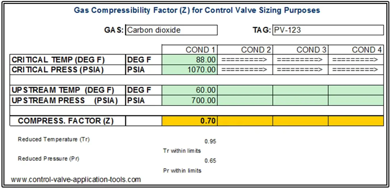
Some time ago I got tired of reading the Charts and made an Excel sheet where I tabulated a lot of reduced pressure and reduced temperature points from the Nelson-Obert charts and included a two-dimensional interpolation scheme that yields a compressibility factor for any gas that I can find the critical pressure and temperature for. Below is a screenshot of the sheet showing a calculation for carbon dioxide.
In this case, assuming a compressibility factor of 1.0 when it is really 0.7 would result in a Cv calculation that would be about 20% high. When the compressibility factor decreases, so does the calculated required valve capacity (Cv or Kv).
Text originally published in 2015, and slightly updated in April 2022, due to the company name change to Valmet.
This Excel sheet can be downloaded from the Worksheets page at no charge at: www.control-valve-application-tools.com

Subscribe to our newsletter
Subscribe now to flow control newsletter and receive the latest insights directly to your email.
SubscribeRead more from Jon F. Monsen
