Determining the control valve pressure drop for control valve sizing purposes
Our guest writer Jon F. Monsen discusses the correct method for determining the control valve sizing pressure drop when the system already exists or has been designed.
When determining the control valve pressure drop to use in a control valve sizing calculation, there are three possible scenarios. 1) You have a control valve specification sheet with process data (including valve sizing pressure drop information) provided by experienced piping engineers in your organization or an Engineering, Procurement, and Construction (EPC) company. 2) When the system exists or is already designed but you must determine meaningful control valve sizing pressure drop information. 3) When you have a say in the system design.
In the case of the first scenario, you will most likely assume that you have reliable information and proceed with the selection of an appropriate control valve, so I will not discuss this case further. In this posting, I will discuss the second scenario, and in a future posting, I will discuss how Nelprof™ control valve sizing and selection software’s unique ability to graph the installed gain of a control valve can be helpful with the third scenario.
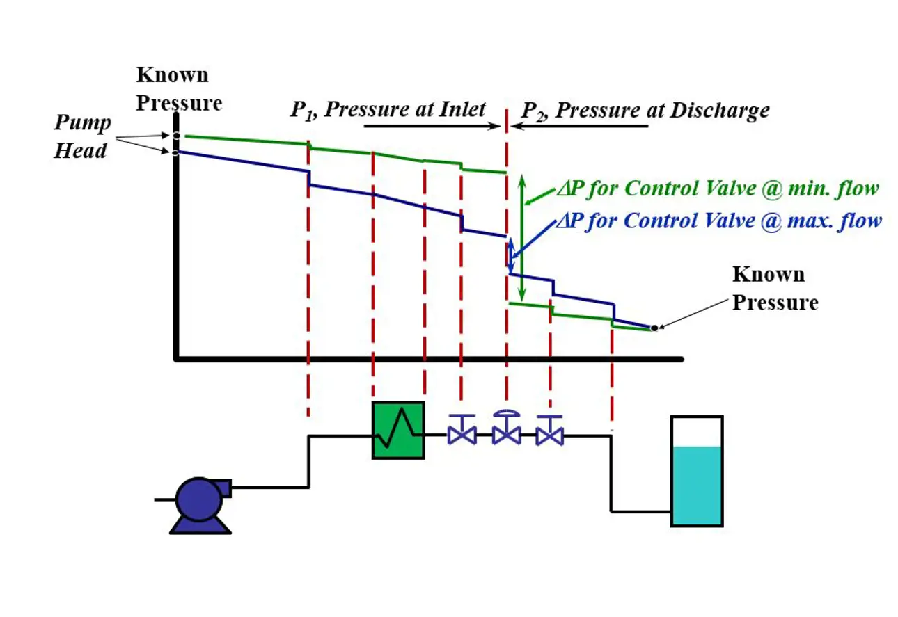
When the system exists or is already designed, what is important to keep in mind is that the control valve DP cannot be arbitrarily specified without regard for the actual system into which the valve will be installed. What must be kept in mind is that all of the components of the system except for the control valve (pipe, fittings, isolation valves, heat exchangers, etc.) are fixed and at the flow rate required by the system (to cool a hot chemical to a specified temperature, maintain a specified level in a tank, etc.), the pressure loss in each of these elements is also fixed. Only the control valve is variable, and it is connected to an automatic control system. The control system will adjust the control valve to whatever position is necessary to establish the required flow (and thus achieve the required temperature, tank level, etc.). At this point, the portion of the overall system pressure differential (the difference between the pressure at the beginning of the system and at the end of the system) that is not being consumed by the fixed elements must appear across the control valve. The correct procedure for determining the pressure drop across a control valve at the flow rates for which you plan to perform sizing calculations is illustrated in the figure below:
Start upstream of the valve at a point where the pressure is known (for example a pump where the pressure can be determined from the head curve, or in the case of a running system, a pressure gauge near the pump discharge) and subtract the pressure loss in each of the fixed elements. When you get to the valve inlet you know P1, the pressure immediately upstream of the valve. The next step is to go to a point downstream of the control valve where the pressure is known (for example, a tank where the head is known) and then work upstream toward the control valve, adding the pressure loss of each of the fixed elements. (You are adding the pressure losses because you are working in the direction opposite to the flow.). When you get to the valve outlet you know P2, the pressure immediately downstream of the valve. The actual pressure drop across the control valve is the difference between the upstream and the downstream pressures, that is, DP = P1 – P2. If you plan to perform sizing calculations at more than one flow rate (for example, at both maximum and minimum design flows) you must repeat the calculation of P1 and P2 at each flow rate, since the system pressure losses (and pump head) are dependent on flow.
Text originally published in 2015, and slightly updated in April 2022, due to the company name change to Valmet.

Subscribe to our newsletter
Subscribe now to flow control newsletter and receive the latest insights directly to your email.
SubscribeRead more from Jon F. Monsen
