Flow control for chemical industry
Improving reliability and productivity of your process

Feeling more pressure from performance demands, regulatory bodies and environmental legislation? In need of a reliable partner to get your high-performance plant planned, built and operating on schedule? We’re here to help you with your process valves – and everything you need at every plant engineering stage – for smooth startup and profitable operation.
High process availability
Improved operational efficiency
Reliability
Life cycle services close to the customers
Reliable valves and services for chemical industry
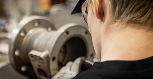
Our experts, with vast know-how of different chemical plant processes and challenges, work closely with you to choose and dimension the right valve for each specific use. And our wide offering of valves ranges from standard to application-specific technologies, ensuring the ideal solution for your particular needs.
What it takes to master the toughest conditions
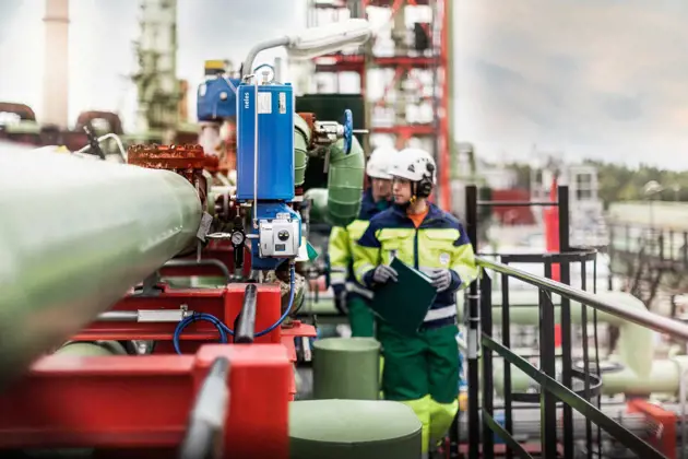
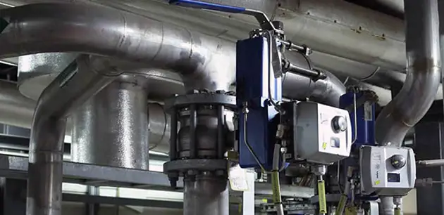
Intelligent valve controllers, advanced diagnostics software and loop tuning are all part of our performance solutions for the chemical industry that provide you with easy, safe and reliable operation.
Valmet is known for providing the widest selection of valves for control, on-off and emergency shutdown applications. Each valve has been tested and certified in the most demanding circumstances to deliver the highest possible reliability. Because operating conditions vary greatly from one process to another, we provide many valve solutions that withstand the heat, abrasive flow media, polymer growth or plugging risks inherent to chemical plants.
Get lifelong benefits and ensure your success
Partnering with us means that you can rely on long-term customer support, determined problem-solving and a broad range of services throughout the lifetime of your chemical plant. From the engineering phase to execution, commissioning and startup through to repairs – we give you exactly the level of support you need to reach your goals. Plus, Valmet is known for its exceptional predictive maintenance planning support that saves you time and money.
We work closely with you to meet all your project requirements and specifications. With decades of experience and dedication to delivering results, we pride ourselves on meeting even your toughest performance expectations. Because for us, every detail matters.
Our global and local comprehensive expert services are available near you. Additionally, you’ll have your own dedicated project execution team to make sure you get everything you need to keep your plant running reliably.
Smart technology utilization in the refining & chemicals industry
Valmet’s smart technologies, when correctly implemented into the process, have the potential to help refining and chemical industry operators improve the utilization rate of data.
Read the expert blogSolutions for different applications in chemical industry


Flow control solutions and services for chemical industry


Insights on chemical industry


