Below are some common illustrations of equipment located on fluids circuit diagrams, followed by descriptions of the most common elements. Later in this article series we will describe some simple hydraulic and pneumatic circuits composed of these circuit elements.
Common groups of fluids circuit elements
Specific fluids circuit elements
Needle valves
Needle valves are used to throttle or shut-off flow of fluids. They usually will vary flow with pressure or viscosity change. Some valves can be pressure and/or temperature compensating.
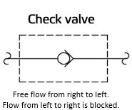
Check valves
Check valves are one way valves, allowing flow in only one direction.
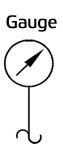
Gauges
Gauges are used to measure the oil pressure at a given point in the system. This is usually measured in PSI or bars. One bar = 14.5 PSI.
Flow control valves
Flow control valves are used to control oil flow in one direction and unrestricted in the opposite direction. "Metered in" control means that the flow controls are controlling the fluid into the actuator, "metered out" is controlling the fluid out of the actuator. Some valves can be pressure and/or temperature compensating.
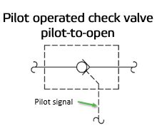
Pilot operated check valves, pilot to open
When the pilot line to a pilot-operated check valve is not pressurized, flow is allowed in one direction but blocked in the opposite direction. When the pilot line in a pilot-to-open valve is pressurized, the check valve is open, allowing flow in either direction.
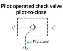
Pilot operated check valves, pilot-to-close
When the pilot line to a pilot-operated check valve is not pressurized, flow is allowed in one direction but blocked in the opposite direction. When the pilot line in a pilot-to-close valve is pressurized, the check valve is closed, blocking flow in both directions.
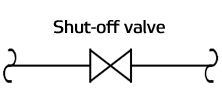
Shut-off valves
Shut-off valves are used to isolate one part of a fluid system from another.
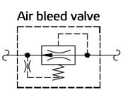
Air bleed valves
Air bleed valves are used to automatically eliminate air bubbles from pressurized hydraulic systems.
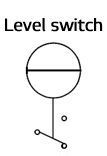
Level switches
One use of a level switch is to detect when the oil in a reservoir is reduced to a minimum operating level.
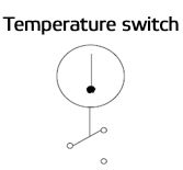
Temperature switches
One use of a temperature switch is to detect when the oil in a reservoir reaches the maximum operating temperature.
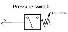
Pressure switches
Pressure switches are use to detect a pressure rise or fall through a set pressure point. These switches may or may not be adjustable.
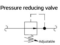
Pressure reducing valves
Pressure reducing valves are used to reduce the pressure in individual circuits.
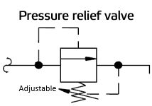
Pressure relief valves
Pressure relief valves are used to limit the maximum pressure in all or part of the hydraulic system.
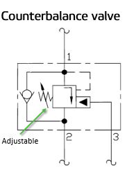
Counterbalance valves
Counterbalance valves are used to control overrunning loads and to support loads should a function be stopped at any point throughout its travel. NOTE: this valve is typically preset and should not be tampered with.
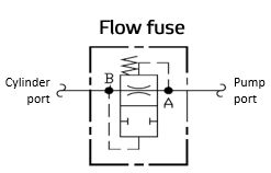
Flow fuses
Flow fuses are normally open valves which close if the pressure difference between the inlet and outlet valves is too high compared to the design setting. The valve can be reset by reversing the direction of flow. When placed inline with an actuator (for example, a cylinder), flow fuses limit the maximum speed of that actuator.
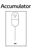
Accumulators
Accumulators are used to store hydraulic energy and to absorb shock in a hydraulic system.
WARNING:
Make sure to discharge all hydraulic energy before working on any components.
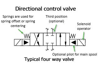
Directional control valves
Directional control valves are used to direct fluid flow into the appropriate lines for the designated operation. These valves are usually electrically controlled.
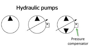
Hydraulic pumps
Hydraulic pumps are used to pump oil from the power unit to other parts of the hydraulic system. Some pumps have control options such as pressure or flow compensators.
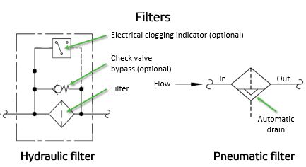
Filters
Filters are used to remove contaminants from fluid.
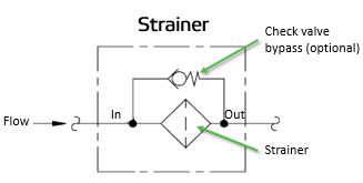
Strainers
Strainers are used to remove large solid from water or oil supply. They may have a check valve bypass.
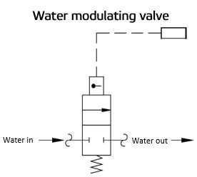
Water modulating valves
Water modulating valves are used for controlling the oil temperature in the reservoir automatically by controlling the volume of water going through the heat exchanger.
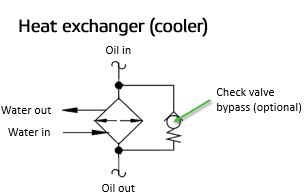
Heat exchangers (cooler)
Heat exchangers are used to remove heat from the circulating oil in the hydraulic system. The most common heat exchanger is water-to-oil but some times air-to-oil units are used. Coolers will cool the fluid.
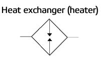
Heat exchangers (heater)
Heaters are used to warm the fluid.
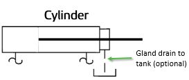
Cylinders
Cylinders are used to convert fluid energy into mechanical linear motion.
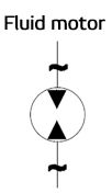
Fluid motors
Fluid motors are used to convert hydraulic energy into mechanical rotary motion.
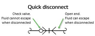
Quick disconnects
Quick disconnects are used to disconnect a line to separate one piece of equipment from another.
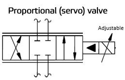
Proportional (servo) valves
Proportional valves are electrically controlled hydraulic valves. These valves proportionally control the hydraulic pressure and/or flow based on an electrical input signal.
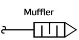
Mufflers
Mufflers are used to reduce the noise of exhausting air.
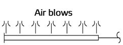
Air blows
Air blows are represented as shown below. The number of blows varies.
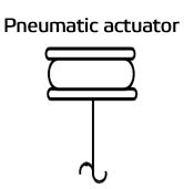
Pneumatic actuators
Fluid actuators are used to convert fluid energy into mechanical linear motion.
For more information about reading hydraulic and pneumatic circuit diagrams, read the next article in this series which describes sample hydraulic circuits, or contact your Valmet representative.