Flow control for copper
From copper concentrates, smelting and electrolysis to copper leaching, solvent extraction and electrowinning
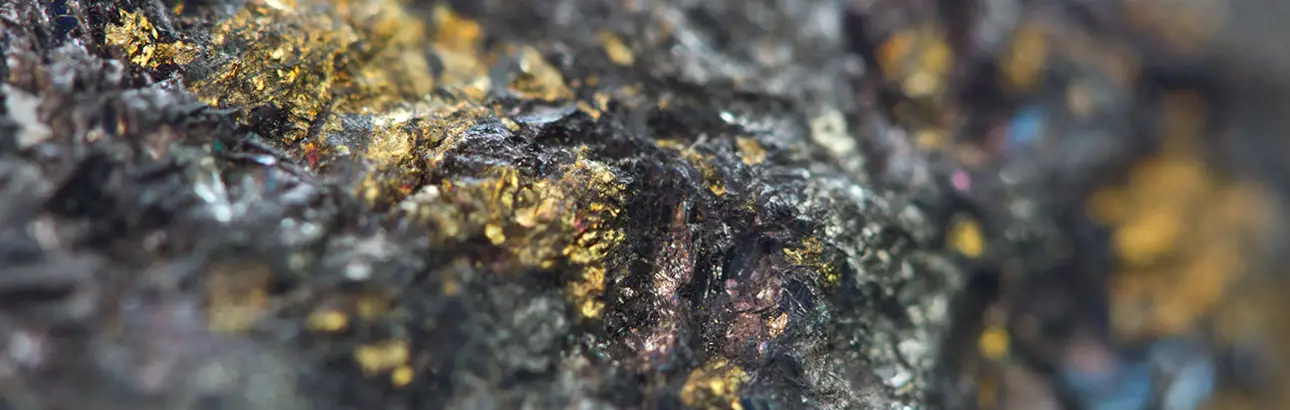
Increasing the efficiency of copper concentrates production, smelting and electrolysis is possible by carefully selecting the optimal valves and pumps for each process. The most common copper ore types, copper oxide and copper sulfide, undergo two different refining processes – hydrometallurgical and pyrometallurgical, respectively. By global copper production volumes, pyrometallurgy is the dominant processing route.
Improved process control increases product yield and profit
Better maintenance planning capabilities to reach plant uptime targets
Preventing unexpected shutdowns and reducing maintenance costs
Minimizing fugitive emissions and increasing safety
Copper refining in a nutshell
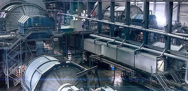
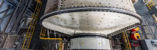
Refining copper starts with crushing and grinding; at some sites, this is followed by hydrocyclone separation. The slurry then moves to a flotation stage where reagents are added to the feed.
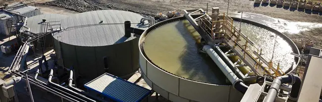
The reagents bind to the copper particles making them hydrophobic. As the air bubbles that are generated in the bottom of the tank rise to the surface, copper-bearing minerals attach to the rising bubbles. The copper-rich froth at the top the tank is then skimmed off and taken to a thickening stage, which is followed by dewatering. The resulting copper concentrate typically contains around 30% copper.
The copper concentrate is transported to a smelter where it is purified at high temperatures. Pyro processing begins with a smelting furnace where the concentrate is converted into molten liquid. The temperatures at this phase are as high as 1200 ᵒC (2300 ᵒF). The hot liquid is then poured into a slag-settling furnace. The output product, copper matte, contains some 60% copper.
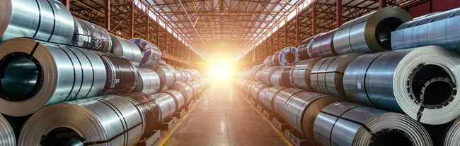
The molten matte then moves to the next furnace, called a converter, where most of the remaining impurities are burned off. The converter produces an output, referred to as blister copper, now at 98% concentration. In the following anode smelter, the purity of the copper increases to 99%. In the final processing step, electrolysis, copper anode slabs are refined by applying electric current. The result is 99.99% pure copper.
LX-SX-EW aims to concentrate the aqueous copper solution from a few g/l to around 40-50 g/l and to eliminate the chloride, ferrous, manganese and other impurities that may cause problems in the downstream electrowinning process.
There are six different methods for leaching: heap, dump, in-situ, agitation, autoclave and vat. The leaching method used at each processing plant varies based on the ore chemistry and local conditions. Heap and vat leaching are common leaching methods.
In vat leaching, the process starts with the crushing, grinding and separation circuit followed by thickening. The slurry then enters vat leaching tanks and moves to solvent extraction through dewatering.
Heap leaching starts with the sprinkling of a low concentration sulfuric acid and water solution on a stockpile (leach pad) of low-grade ore.
The liquid percolates through the stockpile and dissolves copper minerals, producing an approx. 60% copper concentration called pregnant leach solution (PLS). The PLS then flows to a collection reservoir and to the solvent extraction plant; the copper is then transferred from the mildly acid aqueous leach solution to an organic solution.
After extraction, the copper-loaded extractant is fed to the stripping unit, where it is transferred from the organic solution to a strongly acid aqueous electrolyte solution.
This is followed by the final stage, electrowinning, where metal is recovered from the acid solution as it deposits to the cathode plates. In this step, an electric current is passed through a bath of the extracted material causing the copper to deposit onto metal plates and results in a pure form of the metal.
Optimally selected valves and pumps simplify copper leaching, solvent extraction and electrowinning process control
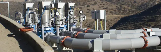
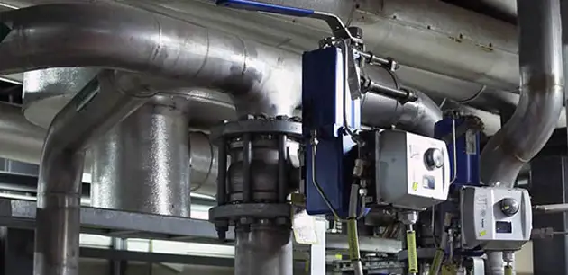
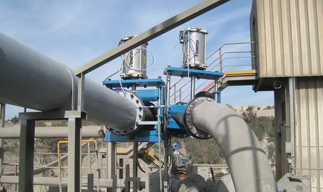
Valves play an important role in the LX-SX-EW process by ensuring that various liquid flows are kept within the optimum range. Because of the demanding requirements for some of the valve installations and the constant acidity, selecting the optimal valves can have a positive impact on the plant’s overall profitability.
Valves for the pregnant leach solution
The pregnant leach solution is the output product of leaching. It forms as sulfuric acid percolates through the ore pile while the copper content of the ore is introduced in the aqueous solution. At some sites, drainage systems move the solution to the next processing stage using gravity; other sites use pumps.
Butterfly and ball valves are good choices for PLS flow control. Chloride sometimes poses a challenge in PLS feed, in which case the valve material selection is an important factor to be considered. For instance, hastelloy steel is a typical choice, as it exhibits a very high resistance against corrosion.
Valves for the raffinate feed
Raffinate is a mild solution of sulfuric acid with a pH typically between 1.2-2.0. When choosing a valve, many of the choices are typically straightforward in terms of size and pressure class, but there are also factors that may need a proper evaluation to ensure the best possible outcome. In addition to material selection, the right body and seat designs ensure that the valves perform at their peak.
Valves for the rich electrolyte solution
In the stripping stage of the process, the copper in the organic solution transfers to an aqueous solution, resulting in a rich electrolyte solution. This solution is piped to the electrowinning stage. Pipe sizes vary from site to site and can be DN1000 or even bigger. As pressures are typically in the lower range, butterfly valves are a good choice and provide the lowest total cost of ownership.
Each ore deposit is unique in its concentration and mineral composition. Therefore, the most economical plant flowsheet varies from site to site. Even though the unit processes might be site-specific, the principle for the processing of sulfide ore remains the same.
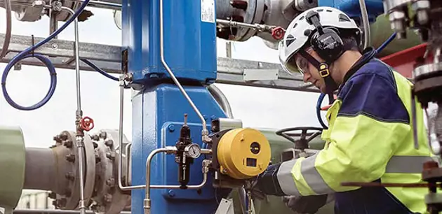
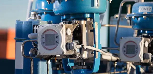
Copper processing plants turn to flow control experts to isolate and control various process flows. In the upstream processing, valves regulate, for example, flotation and dewatering. In the downstream smelting and electrolysis processes, valves control, gas, air and electrolyte solution flows.
Valves for froth flotation
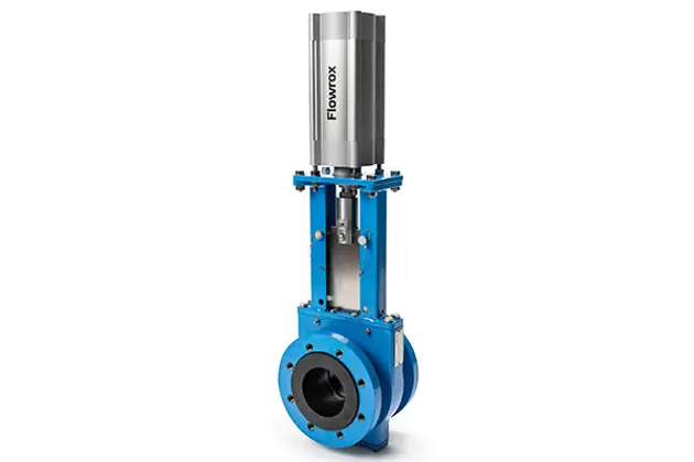
Valves commonly control the slurry feed and discharge, reagent addition and water flows in flotation equipment. Knife gate valves are used extensively in this application.
Another typical valve type is rubber-lined butterfly valve. Segment valves are an excellent solution for the reagent feed and control.
Valves for dewatering
As particles become finer, the resistance against removing water increases. Dewatering can no longer be achieved by gravitation, so pressure must be utilized.
A mechanical filter press is one option for the dewatering service. The machine contains several valves: Pinch valves are typically used in the slurry inlet feed, while the rest of the valves for water and air service often consist of butterfly valves.
Valves for the smelting process
The smelting process is a complex, multi-stage process involving high temperatures and molten liquids. Oxygen and air control are key to a reliable and efficient process.
For these operations, valve materials need to be carefully selected, and cleanliness is of paramount importance due to the inherent danger of oxygen reacting with any grease, oil, or combustible material left in a piping system.
The evaluation of valves for an oxygen application requires an understanding of metallurgy as well as valve geometries.
Valves for electrolysis
The electrolyte solution is piped to the tank. As pressures are typically rather low, butterfly valves are a good choice and provide the lowest total cost of ownership.
Downloads
Valves, pumps, valve automation and services for copper production
Flow control for different applications in mining and minerals processing