Maintenance and operation of press stretchers and guides
Mar 29, 2022
The following stretchers and guides are of Valmet design, but are similar to other OEM designs in the field and therefore illustrative of the processes of stretching and guiding fabrics.
Press felt stretcher
The paper machine has a number of various loop-type fabrics, typically felts, which must have a specific tension so that the paper machine operates properly and so that the control of these fabrics is possible. The travel of the devices which stretch the fabrics, i.e. stretchers, is typically 1200 to 3000 mm depending on the length of the fabric loop, its material and the tension applied.
The fabric is stretched by means of a movable roll which is situated so that as it is being transferred, the length of the fabric loop changes. The roll is mounted by its bearing to the stretcher carriages, and as the carriages move, they also move the roll, changing the length of the fabric loop and stretching the fabric.
The stretching force is created by a pneumatic cylinder in which the suitable stretching pressure is applied. The air motor in the stretcher is not used for changing the tension achieved with the cylinder. The motor is only used for returning the cylinder into operating range by transferring the carriages and hence also the stretching shaft.
A constant pressure of 4 to 5 bar is applied at the air motor.

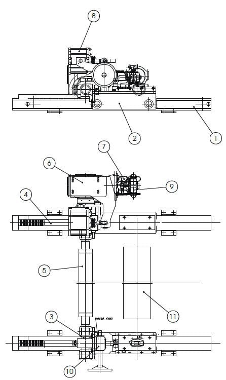
Press felt stretcher, elevation and plan views
- Beam
- Carriage
- Toothed shaft
- Toothed rack
- Cross shaft
- Worm gear
- Air motor
- Pneumatic cylinder
- Remote control valve
- Seam straightening device
- Roll
Design of the stretcher
The stretcher has carriages (2) on the tending and drive sides. Each carriage has wheels and moves along a beam (1), transmitted by a toothed rack (4) and toothed shaft (3). Synchronous simultaneous movement of the carriages on each side is by means of a cross shaft (5); the cross shaft also transmits the torque required by the movement.
The drive (6,9) for the stretcher is placed on one carriage, usually on the drive side, i.e. the drive moves with the carriage. The maximum carriage travel is limited by end stoppers which withstand the load of the stretcher.
The stretching force is created by pneumatic cylinder (8) in which the suitable stretching pressure is applied. The air motor (7) in the stretcher is not used for changing the tension achieved with the pneumatic cylinder. The motor is only used for returning the pneumatic cylinder into their operating range by transferring the carriages and hence also the stretching shaft.
An optional seam straightening (10) device is placed on the drive or tending side carriage, where it is possible to move the bearing of the roll (11) in the machine direction ±30 millimeters by means of a worm gear.
Initial situation after the installation or change of fabric
The fabric is slack, the carriages have been run to a minimum distance and there is no pressure in the motor or pneumatic cylinder.
On the pneumatic cylinder, set a pressure which is 50% of the pressure corresponding to the desired tension. The pressure applied at the pneumatic cylinder generates a force against the torque arm, causing the combination of air motor and gear to turn upward in relation to the carriage. Once the turning angle has reached an angle of approx. 7 degrees, the control valve sends a starting signal to the air motor. The air motor starts and moves the carriages and stretching roll in the stretching direction, first removing any slack from the fabric and thereafter stretching the fabric until the set initial tension is achieved. At this stage, the stretching roll remains "floating" against the fabric due to the stretching force.
The fabric is stretched to the final tension by increasing the stretching pressure applied at the pneumatic cylinder. The air motor should now be at an angle of approx. 2 to 3 degrees.
Decrease the stretching pressure applied at the pneumatic cylinder. The combination of air motor and gear starts to turn down until the carriages and the stretching roll move slightly toward the slackening direction, simultaneously slackening the fabric. Once the turning angle has reached an angle of approx. -7 degrees, the control valve sends a starting signal to the air motor. The air motor starts and moves the carriages and stretching shaft slightly in the slackening direction until the pressure in the pneumatic cylinder counteracts the force caused by the tension of the fabric and turns the combination of air motor and gear backward a few degrees, whereby the air motor stops. The more the stretching pressure in the pneumatic cylinder is decreased, the more the carriages and stretching shaft move and the tension decreases.
Once the stretching roll has been run sufficiently or completely to the slack end, close the stretching pressure applied at the pneumatic cylinder and the constant pressure applied at the air motor. If it is necessary to prevent the fabric from becoming slack during standstill when the stretching pressure for the pneumatic cylinder needs to be decreased, close the constant pressure for the motor before decreasing the stretching pressure.
Other issues to be observed:
- When the tension of the fabric increases as a result of shrinkage (such as drying during standstill) or when its tension decreases as a result of elongation, the position of the stretching shaft changes automatically and the tension remains constant, provided that both the stretching pressure and constant pressure are applied.
- The control desk should contain a pressure gauge and control valve for stretching pressure. The stretching pressure corresponding to the tension of the fabric is indicated by a fabric tension nomogram provided by the fabric stretcher OEM.
Maintenance of the stretcher
The cleaning of the toothed racks must be done when necessary before slackening the fabric.
Annual procedures
- cleaning (beams, toothed shafts, toothed racks, pneumatic cylinder)
- inspection (beam rolling surfaces, shape of toothed shafts and racks, pneumatic cylinder)
Quarterly procedures
- Inspect air motor exhaust silencers
The air motor exhaust silencers must be checked to verify they are not choked. If a silencer is choked, it will prevent the air motor functioning properly. In this case the silencer must be changed. In very harsh conditions (mainly at press basement positions), the silencer could be replaced with a short (approx. 0.5 meter long) hose.
Issues to be paid attention during inspection:
- tooth clearance at normal tensioning area
- tooth rolling surface wearness at normal tensioning area
- roller clearances at normal tensioning area
If the inspection didn’t show any need for further action, the stretcher can be lubricated. Note that the rolling surfaces of beams, toothed shaft and rack should also be lubricated.
Check all oil filling levels of components.
Press automatic guide
The paper machine has a number of various loop-type fabrics, wires and felts, which must have a controlled position in the cross direction of the paper machine (usually in the middle) so that the paper machine operates properly and as designed. The travel of the devices which guide the fabrics, i.e. guides, is typically plus/minus 40 to 70 mm, depending on the machine width, material of the fabric and the tension applied.

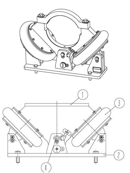
Press automatic guide, isometric and elevation views
- Lever arm
- Pedestal
- Bellows
- Center pin
Design of the automatic guide
The guide is made of welded steel plate and consists of a pedestal and a lever which has been mounted by a pivot pin at its bottom section. Rubber bellows are mounted on both sides of the lever at an angle of 45 degrees. The lever has a ball-shaped hole into which the bearing housing of the guide roll is mounted. This way, the lever is the bearing holder of the roll and also suspends the guide roll.
The lever moves by its pivot pin from one side to the other by the effect of the pressure in the bellows. The maximum travel of the lever is limited by a stopping pin.
The fabric is guided by a roll which rests against the surface of the fabric and rotates drawn by the fabric. The roll is normally mounted by its tending side bearing to a bracket which moves in the direction of the fabric. As the bracket moves by the effect of the air bellows, it also moves one end of the roll while the other end of the roll remains stationary. The force moving the fabric is generated by the difference between the running direction of the fabric and the running direction of the roll shell. The force thus generated tends to transfer the fabric through friction, since the roll has been mounted on bearings so that it remains in place axially.
Principle of guiding operation
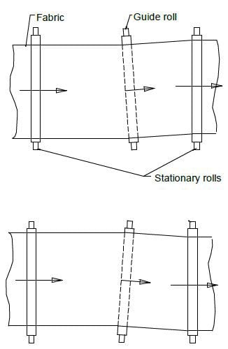
The guiding of fabrics is based on the principle that the fabric will always leave a roll perpendicular to its rotational axel. This dictates that the fabric will always move toward the end of the roll it encounters first.

Principle of guiding operation
The fabric is guided by a guide roll which rests against the surface of the fabric and rotates drawn by the fabric. The roll is normally mounted by its tending side bearing to a guide which moves in the direction of the fabric. As the guide moves by the effect of the air bellows, it also rotates the guide roll pivoted at drive side end.
The automatic guide is controlled or positioned by a palm guide valve. The edge of the fabric remains in contact with the palm guide valve and continuously follows it. As the fabric moves toward and away from the palm, the palm guide valve adds and bleeds air from the guide controlling bellow. The controlling bellow moves the end of the guide roll to continuously track the fabric during machine operation.
Maintenance of the automatic guide
WHEN SERVICING THE GUIDE, MAKE SURE THAT THE PNEUMATIC PIPES HAVE BEEN CLOSED AND THAT THE PIPELINES FOLLOWING THE VALVES HAVE BEEN DEPRESSURIZED!
The entire automatic guide mechanism has been designed service free. Monitor the operation of the fabric guide valve, and test its operation regularly by moving the guide plate to detect potential clogging or jamming of the valve.
DO NOT MOVE THE GUIDE PLATE BY HAND WHILE THE MACHINE IS RUNNING, BUT USE A TOOL SUCH AS A WOODEN BATTEN!
At least once a year, clean the guide carefully and inspect its pedestal and lever arm. Check the condition and clearances of pins, and the general condition of lockings. Inspect the condition of the rubber bellows. If the rubber bellows are still in full operating condition, they should feel soft and have no cracks. Hardened or cracked bellows must be replaced immediately. In conjunction with the replacement of bellows, it is recommended to seal the gap between the bellows and the plate which is contact with the bellows with, for example, silicon.
If the inspections require no further measures, grease the guide.
If necessary, your OEM service personnel are prepared to service the guide and to ascertain its condition.
Press manual guide
The purpose of the manual guide is to keep the automatic guide within its operating range. The fabric guide mechanism operates automatically when the paper machine is running, continuously centering the fabric as guided by the fabric guide valve of the guide.

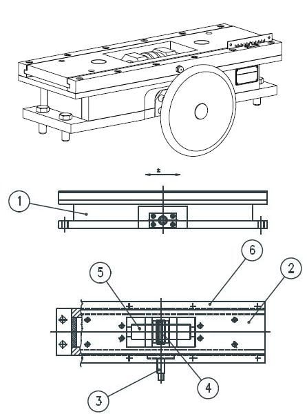
Press manual guide, isometric, elevation and plan views
- Frame
- Slide plate
- Worm shaft
- Worm wheel
- Transfer screw
- Slide rails
Design of the manual guide
The guide is made of welded steel plate, and consists of the frame
and slide plate. The slide plate is mounted on the frame with two slide rails. The slide plate is moved by a worm gear installed inside the guide. A guide or roll bracket can be mounted directly on the slide plate.
Maintenance of the manual guide
The entire manual guide mechanism is designed to be service free. Test its operation regularly by moving the guide by rotating the hand wheel back and forth few times.
At least once a year, clean the guide carefully and inspect the condition of its frame, slide plate and slide rails. Also, check the condition and clearances of the gear inside the guide and the general condition of the lockings.
For more information on maintaining stretchers and guides, contact your Valmet representative.