The purpose, operation and maintenance of belted threaders
Oct 6, 2015
Operation of a belted threader
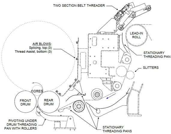
On a winder, the sheet is typically threaded from the unwind stands to the cores in the drum pocket using any combination of manual threading, belted threaders, threading pans, air blows, web holder or rear drum suction. The threading devices are typically positioned for use with a center wedge tail. Threading up to the drum pocket is carried out with the winder running at a decreased speed. The following figure (Figure 1) shows an example of a winder threading system that includes a lead-in double belted threader, stationary and pivoting threading pans and air blows.

Figure 1 Example threading and splicing equipment on a winder
During normal operation the belted threaders are in a home position, away from the web (as shown in Figure 1). During threading, the belted threader frames are pivoted to contact an adjacent roll such as a lead-in or slitter table roll, forming a threading nip. The threader nips the tail against the roll, and as the belts are rotated, pulls the tail onward through the winder. This allows the operator to keep clear of dangerous areas such as slitters during the threading process.
A belted threader may have one or two belted sections, depending on the application. In the example shown in Figure 1, the belted threader nips a lead-in roll and has two belted sections. In this case, the first (upstream) belts will raise off the lead-in roll as the tail progresses, leaving only the second belts to propel the tail onward.


Installing belts


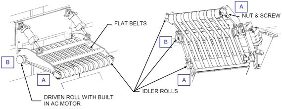
Figure 2 Typical belt threader assemblies (number of belts, rolls, cylinders varies)
- Where applicable, make sure that the drive to any driven roll is locked out.
- Remove air pressure from the pneumatic circuit.
- Slacken the tension in the belts by loosening the jam nut and backing off the hex screw of the idler roll. Refer to "A" in Figure 2.
- Remove the outer roll(s).
- Remove the idler roll. Refer to "B" in Figure 2.
- Place the new belts over the inner roll in the correct sequence (for two belt systems) and re-install the roll or idler rolls in reverse order.
- Place the belts over the outer roll in the correct sequence, and re-install the roll. (In a two-belt design, do one roll at a time.)
- Adjust belt tension until the belts turn the rolls and track straight when rotated against the adjacent roll.


Maintenance schedule

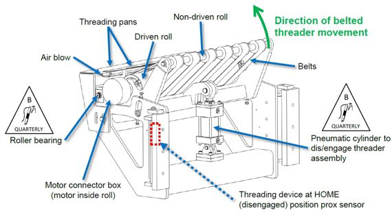
Figure 3 Typical Belted Threading Assembly
Daily maintenance
- Check for proper operation.
- Check air blow(s) for sufficient air flow. Clean if dirty.
Monthly maintenance
- Check belts for excessive wear and proper adjustment. If misaligned, the web will not travel straight, making web threading difficult.
- Inspect pneumatic cylinder for operation and leaks. Repair kits should be available.
- Check for proper operation of proximity switch(es).
Quarterly maintenance
- Lubricate pneumatic cylinder rod eye and clevis.
- Lubricate belt roller bearings.
Annual maintenance
- Inspect idler roll bearings and pivot bushings for wear and replace as needed.
- Inspect the components during a scheduled down.


NOTE: Type B lubricant is grease lubrication without EP additives.


For more information on training operators and maintenance personnel or for assistance with your belted threaders, contact your Valmet representative.