A brief introduction to machine vibration analysis techniques
May 9, 2017
All mills conduct some sort of vibration analysis as part of their preventative maintenance programs. Most measure mechanical vibration to identify bad pump and roll bearings, roll cover condition, nip vibration, roll balance, etc. Some mills have even taken a further step forward by analyzing basis weight, moisture, caliper, and opacity signals from their process gauging scanners and pressure pulsations in wet end approach piping and headbox in order to identify variations in product quality. The goal in measuring all of these points is to determine how severe the vibration is and to identify the root cause of the vibration in order to correct the problem before some type of failure or customer complaint occurs.
Vibration analysis is a complicated field of study so in this brief article we can't go in depth about the theory and technology. To put it simply, vibration analysis is the process of obtaining raw time wave signals of motion and mathematically breaking them down into their original waveforms of individual frequencies. From that data, a frequency spectrum is created.

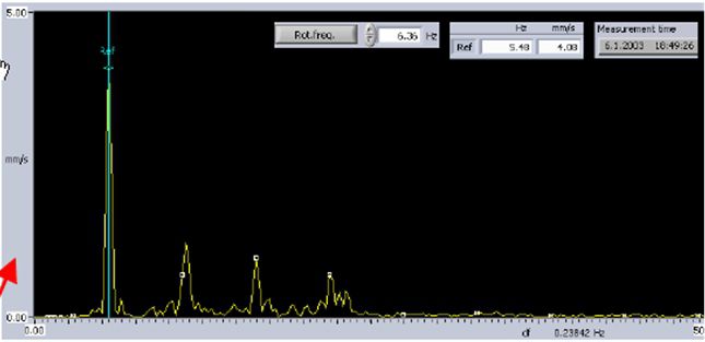
Frequency spectrum and harmonics example (Velocity vs Frequency)
A frequency spectrum consists of frequency on the x-axis and amplitude of the frequency on the y-axis. It is graphically obvious where the original peak vibrations are. However, this is where the real work begins.
Once you know the critical frequencies that are present in the original wave form, you have to find what components on the paper machine vibrate or rotate at the same frequencies, or multiples of these frequencies. Many spectra will have a dominant frequency followed by evenly spaced peaks of lower amplitude. These are called harmonics.
Most root causes of low to high frequency vibration are defects in bearings (ball pass frequency, inner and outer race frequency, axial movement frequency, etc.), gear mesh frequencies, nipped roll imbalance or cover problems, press felt condition, and wet end pump and piping equipment. Very low frequency vibration normally comes from process control systems and is better analyzed using the mill DCS or a process database such as PI or Aspen.
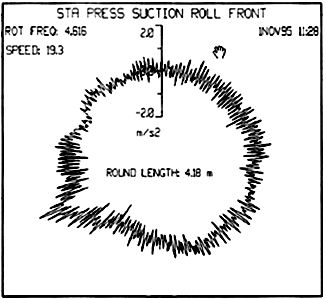
One other vibration analysis technique for identifying the root cause of the vibration is called synchronous time averaging (STA). It uses a rotational signal from a roll, pump shaft, pressure screen rotor, or press felt trade line (called a trigger) to synchronize the raw wave form based on position of the rotating object.

STA Polar Plot – Broken inner race on roll bearing
The resulting diagram is a polar plot of the vibration in regard to the position of the trigger object. Polar plots are easy to understand and are good for identifying barring in rolls and comparing an object's vibration frequency and amplitude over time.
For more information about vibration analysis and its uses to diagnose, prevent and correct problems on your machinery, contact your Valmet representative.