Inspecting dryer cans - guide and recommended procedures
Dec 8, 2020
This article covers recommended types of dryer inspection and their frequency. Regular paper dryer inspections should be a part of a mill's maintenance program. An inspection program is a necessary means to detect early signs of dryer component failure in an effort to maintain a safe working environment and avoid costly extended downtime.

 |
CAUTION: Read all pertinent safety instructions before performing any of the operating or maintenance procedures in this guide. |

Paper dryer inspection
The following is a list of the types of inspections to be performed on a paper dryer:
- External visual inspection; operating, idle and shutdown modes.
- Internal visual inspection.
- Ultrasonic shell thickness (UT) measurement.
- Ultrasonic check (UT) of dryer head capscrews.
- Magnetic particle testing (MT) of dryer heads.
The inspection frequencies that Valmet recommends are:
Immediate
- External visual inspection after; an accident, severe sheet wrap or wad, and felt wrap.
- At first sign of steam leakage.
One year intervals
- Internal visual inspection for; balance weights, erosion under syphon pick-up, and condensate piping.
- External visual inspection for; doctor wear.
Two year intervals
- Dryer head capscrews.
Five year intervals
- Ultrasonic shell thickness measurement.
- Magnetic particle testing of dryer heads
A possible strategy for the five year interval inspection is to perform inspection on 20% of the dryers each year, thereby reducing the length of each outage and the labor required.
Written procedure and record retention
It is essential that a written procedure, including maintaining detailed records, be established to ensure that record retention of the operating history of each dryer be maintained so that one can establish the history of the dryer, and justify its integrity to the insurance underwriter and/or governing jurisdictional inspectors.
This record should contain the following items:
- All ASME Coded dryers should have an ASME U- 1 or U-1A Manufacturer's Data Report. The Data Report is important since it is a record of the maximum allowable pressure, materials, shell and head thickness (new condition), etc. The dryer is traceable to the Manufacturer's Data Report by means of the manufacturers serial number and National Board number stamped on the identification nameplate attached to one of the heads or stamped in one of the dryer heads.
- Assembly drawing of the dryer.
- Non-ASME Coded (older) dryers. If information is not available from original manufacturer, mill personnel must develop their own record file. (Alternately have the dryers measured and a drawing prepared.)
- External and internal visual inspection.
- Ultrasonic shell thickness (UT) measurement.
- Ultrasonic check (UT) of dryer head capscrews.
- Magnetic particle testing (MT) of dryer heads.
- Any repairs made to dryers.
External visual shell inspection
There are several things that should be looked for when dryers are in operation. Paper machine operating personnel should routinely visually examine dryers for:
- Steam leaks
- Unusual bearing noise
- Vibration
- Improper operation of condensate removal system.
If any of the above are found, these items should be noted for additional inspection when the dryers are stopped.
Idling dryers are stationary but have not been opened. They may be pressurized. As with operating mode inspections, thorough visual inspections should be made on idle mode dryers by the operators for:
- Broken capscrews
- Signs of steam leaks: a) Steam leaks at the head to shell joint. (This may cause contaminated capscrews to fail due to stress corrosion cracking.) b) Steam leaks through casting porosity or cracks. (This requires immediate action.)
The most detailed inspections are performed when the dryers are "shutdown" (stationary and cool). An external visual inspection of the dryer face should be made for:
- Doctor wear
- Surface imperfections
- If necessary, a PI tape measurement to determine if any change has occurred in dryer diameter. The dryer shell thickness could decrease due to outside diameter wear. (Severe wear would normally affect sheet runnability, however, shell thickness awareness must be part of an inspection program.)
If a crack should be discovered in the dryer shell, replacement of the dryer shell should be considered immediately, as additional cracks may develop, and some may progress and link up until the shell fails. Steam should be shut off to a dryer immediately upon discovery of a crack.
Internal visual inspection
Appropriate safety procedures should be followed before any internal inspections are performed. The following procedure is recommended for entering a paper dryer to ensure a safe working environment:
- Before the dryer is entered, all the proper stops must be installed and secured. The dryer drive and inching drive (if applicable) must be disconnected and locked out with the lock or locks of the personnel who will be entering the dryer. If a dryer has been disconnected from the gear train, it is important that freewheeling not be allowed.
- The inlet steam and outlet condensate lines must be physically disconnected and blanked off ahead of the dryer inlet and outlet.
- The dryer must be allowed to cool.
- When the manhole covers are removed, the dryer must be thoroughly ventilated by some method of mechanical exhaust or blower system, which is arranged to avoid recirculating stale or contaminated air. Oxygen deficiency tests must verify that the oxygen concentration is stable and maintained at not less than 19.5 or more than 23% in the air by volume. Explosion meter tests, taken where there is any possibility of an explosion or flammable gas or vapor present, must not exceed 25% of the "lower explosive limit". Tests must be taken of the concentration of a toxic or hazardous substance (such as gas, fumes, vapor, mist or dust) if present or suspect it shall not exceed the threshold limit value per OSHA. Subpart Z - "Toxic and Hazardous Substances." 1910.1000 "Air Contaminants". The graphic following this section is a suggested vessel entry form to be filled out in triplicate.
- After the dryer is ventilated, the exhaust or blower system shall be kept operating to provide a continuous supply of fresh air to the dryer.
- Lighting inside the dryer shall be of low voltage or battery operated and protected.
- A worker shall never enter a dryer unless an attendant is outside the dryer. The attendant must not leave the dryer at any time or for any reason while the worker is inside.
- Chemicals or material capable of giving off hazardous fumes must not be taken inside of the dryer without proper safety equipment.
- A dryer lacking permanent access to enter through the manhole must have a ladder secured in place until the work is finished and the manhole replaced. It is the responsibility of the individual or individuals entering the dryer and their supervisor to make sure the above procedure is followed. Questions regarding any of the procedures are to be directed to the supervisor of the work group assigned to the dryer maintenance.
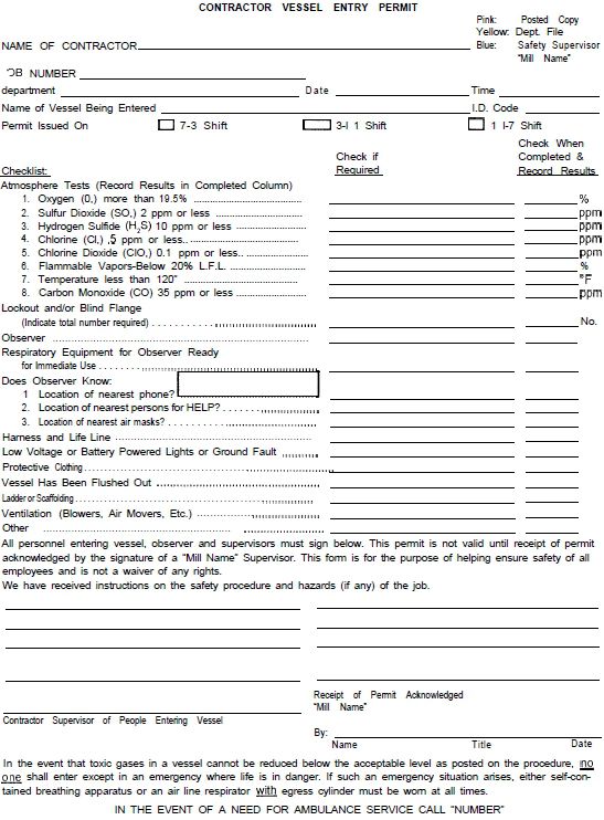
Sample contractor vessel entry permit form
The internal visual inspection shall consist of the following items:
- Inside erosion due to loose condensate parts or balance weights. (Loose parts must be repaired or removed for future repair immediately to prevent damage from tumbling.)
- Inside erosion under the syphon due to steam and condensate flow.
- Inside erosion due to condensate in flooded dryers acting on balance weights and manhole reinforcement.
- Check balance weight attachment condition.
- Check when stationary syphons are used for any grooving of shell I.D.
- Check spoiler bar installation and condition, if spoiler bars are present.
When the internal visual inspection is complete, and the dryer manhole is to be closed up, it is important that the manhole cover is correctly installed to prevent it from becoming loose, with potential of injuring personnel or damaging equipment. It is important that properly tightened locknuts be used. Many Beloit dryers were originally furnished with special split locknuts which may need adjusting after removal. This split nut is adjusted by closing or opening the split with a hammer and/or hammer and screwdriver to produce sufficient drag or friction between threads of nut lock and stud.

 |
CAUTION: Over-adjustment will damage threads! |

Manhole and handhold studs or "T" bolts are grade 2 steel. To prevent loosening or over-torquing, it is necessary to lubricate threads with thread lubricant and tighten nut according to the following chart.
| Thread diameter | Torque |
|---|---|
| 5/8" | 40 ft-lbs |
| 3/4" | 69 ft-lbs |
| 1" | 160 ft-lbs |
Warm-up dryers slowly following a proper procedure, and retorque manhole nuts after one to three hours.
Warm up procedure
It is recommended that a controlled warm up procedure be followed to avoid excessive stress concentrations in the dryers due to large variations in temperature. The controlled warm up should be tailored to your operation. Valmet recommends the following steps in warming up the dryers from a room temperature condition:
- Run dryer at crawl speed and insert 5 psi steam pressure and warm the dryers for l-1/2 hours. Speed may be increased after admitting steam.
- Slowly increase the steam pressure to 30 psi and run 45 minutes. Speed may be increased to operating speed.
- Slowly increase the steam pressure to 60 psi and run for 45 minutes.
- After 3 hours lapse time in warm up cycle the steam pressure can be increased to operating pressure.
If machine has only been down for four to eight hours the length of time for Step 1 may be reduced.
If machine has been down for four hours or less omit Step A and reduce the time of Steps 2 & 3 to 30 minutes each for a total warm up time of 1 hour.
Ultrasonic shell thickness measurement
Four longitudinal scans, 90° apart, should be performed along the entire external length of the dryer shell. These scans should be continuous in nature, noting the readings every 12 inches. See the graphic following this section for a suggested form for recording the measurements taken. When using this form, a standardized reference point on the dryer should be established for continuity. It is suggested that the centerline of the manhole on the tending side of each dryer be designated as 0°. Measurement quadrants are than designated clockwise as 0°, 90°, 180° and 270° while facing the tending side of the dryer.
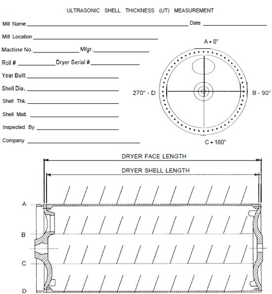
Sample ultrasonic shell thickness mearurement form
Ultrasonic check of dryer head capscrews
Capscrews should be ultrasonically inspected to see if their shanks are cracked. The ideal calibration standard is a sample bolt which is identical in geometry and material to those which are being inspected. The graphic shows how these spare bolts can be notched for use as calibrations standards.
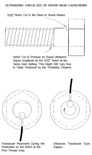
Notching of capscrews for ultrasonic check
The capscrew heads must be prepared by removing any substances or features which will interfere with ultrasound transmissions.
Light grinding may be required to do this, but do not remove ASME bolt identification markings, as they must remain visible.
At least 20% of the bolts should be ultrasonically inspected on a given dryer head. Should a cracked capscrew be found, then all capscrews on that dryer are to be inspected.
The transducer head should not travel beyond the diameter of the shank or false indications may be noted from the underside of the capscrew head. A socket-like template may be used to restrict transducer movement to the shank diameter. See the graphic for this template design.
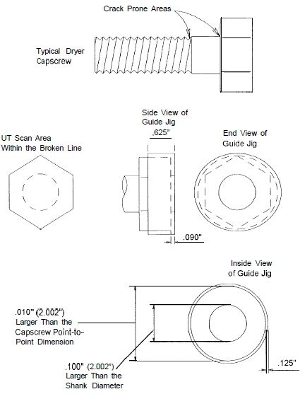
Guide jig to restrict transducer movement
The next graphic is a form that may be used for documenting the findings of ultrasonic testing of dryer head capscrews. When using this form, a standardized reference point on the dryer should be established for continuity. It is suggested that the centerline of the manhole on the tending side of each dryer be designated as 0°, and the capscrews be referred to in clockwise rotation from this point while facing the tending side of the dryer.
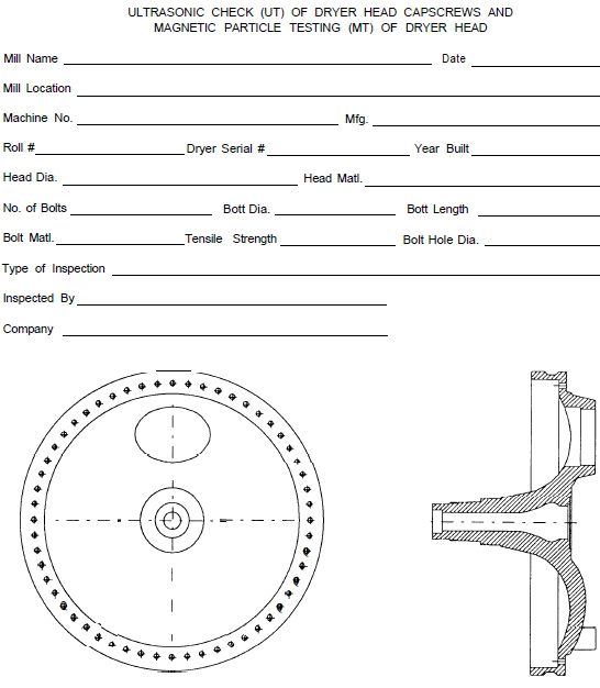
Sample ultrasonic and magnet particle testing of dryer capscrews form
If a leak is found in the dryer-to-shell joint, the capscrews in this area should not be tightened or retorqued but replaced immediately upon leak detection.
Installing and torquing new capscrews
When installing a new capscrew, use ASME Code designated material with specification SA 354 Grade BC. Follow the procedure for installation according to OEM drawing tightening specs. The threads and washer face of the capscrew must be lightly lubricated with thread lubricant. Install the new capscrew and torque to the following amount of torque.
| Capscrew size | Torque |
|---|---|
| 3/4" | 185 ft-lbs |
| 7/8" | 300 ft-lbs |
| 1" | 450 ft-lbs |
Under no circumstances should paper dryer head capscrews be retorqued.
Over-torqued dryer head capscrews
Valmet has been advised that paper mills will, at times, retorque dryer head capscrews in an effort to stop steam leaks at the dryer head to shell joint. This practice often leads to cracked or broken dryer head capscrews which can result in accidents that damage machinery and are a threat to personal safety.
Contact your dryer OEM representative for proper bolt tightening specifications.
A method of sealing leaks in dryers is covered in Valmet's Paper Machine Maintenance course. Contact your Valmet representative for more information.
Magnetic particle testing (MT) of dryer heads
The preferred method of magnet particle testing is wet fluorescent medium, due to humidity or the dryer heads being damp from the cleaning process.
The dryer heads must be cleaned to remove dirt, grease, scale, and other surface contamination. MT can provide successful inspection over clean, tightly adhering paint coatings of paint thickness no more than 10 mils (.25 mm); one coat of high temperature aluminum paint = .4 mils when dry. However, when MT inspection is to be performed over painted dryer heads, appropriate calibration tests to insure satisfactory inspection sensitivity are recommended.
MT inspection is to cover 100% of the dryer head surface, with special attention paid to the areas around the bolt holes, the manhole, and the radius juncture between the journal and head surface.
When any irregularities are found, they should be ground out to reveal good base material by MT inspection again. Irregularities should not be ground out any deeper than .25 inch, and the opening size on the surface should be a ratio of 3:1 to the depth, radiusing the surface edges. Once a crack is discovered, replacement of the head should be considered immediately, as additional cracks may develop, and some may progress and link up until the head fails. Steam should be shut off to a dryer immediately upon discovery of a crack.
Content for this article comes from the following sources:
- Guidelines for the inspection and nondestructive examination of paper machine dryers, TAPPI
- Loss prevention data - paper machine dryer rolls, Factory Mutual System
- Paper machine safety, Partners in Productivity, Beloit Corp
- Dryer safety: care of dryer cylinders - manhole cover stud nut tightening, Safety alert, Partners Paper Machine News, Beloit Corp
- Paper dryer head-to-shell capscrews, Safety Alert, Partners Paper Machinery News, Beloit Corp
- Dryer safety: over torqued dryer head capscrews, Partners Paper Machinery News, Beloit Corp
For more information on dryer inspection, contact your Valmet representative about Valmet's Paper Machine Maintenance course, or see the Related Links of this article.