Reel primary arm nip relief methods reduce bottom waste at turnup
Jul 9, 2019
Reels that are comprised of primary and secondary arms are the most common types of reels in use today. Even the most modern of designs incorporate this type of combination. Excessive bottom waste can occur without sufficient primary arm nip relief.
One important design modification over the years centers on the function of the primary arms and how they impact turnup efficiency and paper losses at the spool. This modification changes the empty spool to reel drum nip pressures by incorporating primary arm nip relieving cylinders. These cylinders are mounted below the new spool bearing housings and push up against the weight of the spool and the force of the spool clamps.
By doing this, the nip pressure is not only controlled at turnup position, it also allows the nip force to be controlled as the primary arm travels down the reel drum. When the spool contacts the secondary rails, the effect of spool gravity on the nip pressure is zero and only the primary arm spool clamps provide the nip pressure. Bottom waste is minimized with smooth control at initial turn-up and through the turn-up sequence.
Typical turn-up procedure
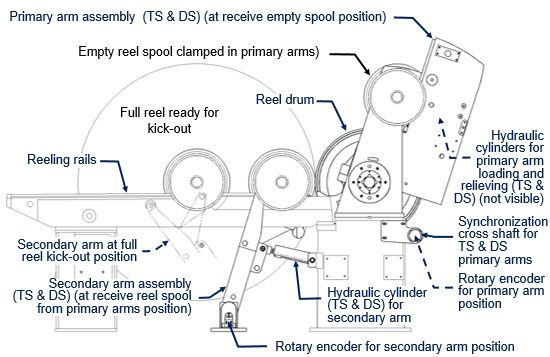
Below is an example layout of a reel with primary and secondary arms and rails.

Overall layout of reel with primary and secondary arms, kickout rails and secondary arms
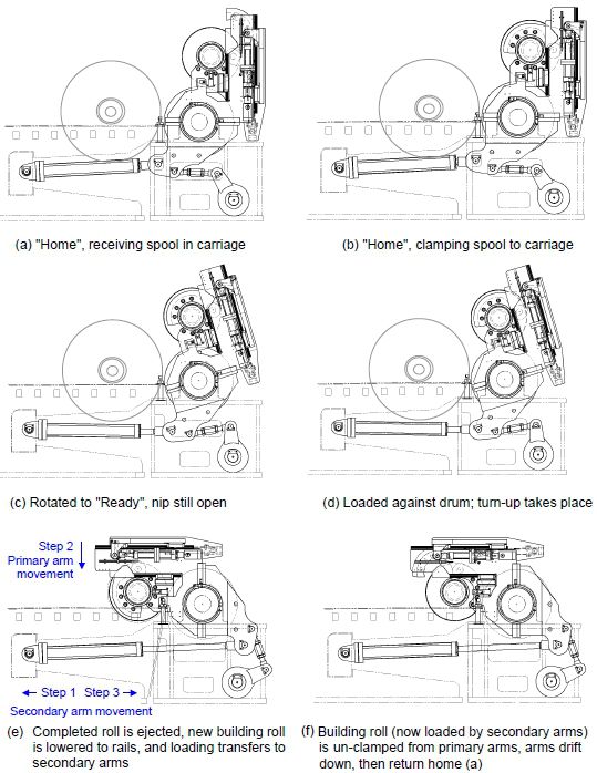
Typically, an empty spool is lowered into the primary arm assembly in preparation for the next turn-up while the current parent roll is still building. At this time, the primary arm assembly is in its "home" (fully raised) position and the clamping arms are open. An empty spool is lowered onto the carriages, guided by the spool guide assembly as seen in (a), in the following figure. The clamping cylinders then close the clamp arms to lock the spool to the carriages (Fig b). Guide blocks and rollers assure proper seating of the reel spool.

Typical movements of the primary arm assembly during turn-up
When the building parent roll approaches completion, the turn-up sequence (when the web is transferred from the completed parent roll to the new spool) begins. A spool starter is applied to the reel spool to bring it up to speed with the reel drum. Once a speed match is achieved, the turning cylinders rotate the primary arms to the "ready" position, above the drum (Fig c).
Once in the "ready" position, the relieving/loading cylinders automatically lower the spool against the drum (still clamped between the carriages and clamping arms). At this point, the nearly completed parent roll and the new spool are both loaded against the drum simultaneously. The turn-up device is actuated and turn-up occurs (the web is transferred to the empty spool). See Fig d.
After turn-up takes place, the completed parent roll is moved away from the drum (using the secondary arms), and the turning cylinders rotate the primary arms further to lower the new building roll to the reeling rails (Fig e). The relieving/loading cylinders continue to load the new building roll against the drum.
As the new roll builds, the primary arms drift slightly downward while the spool remains clamped to the carriages. Meanwhile, the secondary arms move toward the drum and under the spool journals. The loading force is then smoothly transferred from the primary arm assembly to the secondary arm assembly.
After loading has been transferred to the secondary arm assembly, the primary clamp arms open to release the roll (Fig. f), the carriages raise, and the primary arm assembly is raised back up to the "home" position. Another spool is then lowered onto the carriages in preparation for the next turn-up.
One pair piggybacked vs. two pair of hydraulic cylinders
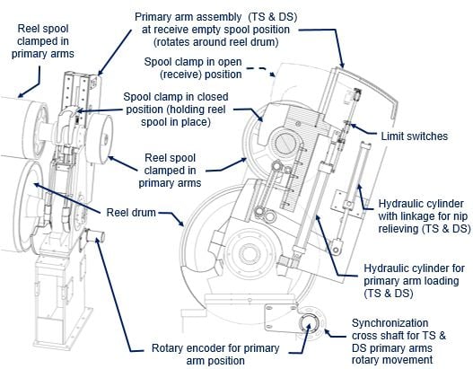
Some reels use a separate pair of TS & DS hydraulic cylinders (4 total) for the relieving/loading function and the nipping function. Other reels use piggybacked TS & DS hydraulic cylinders (2 total) to handle these functions. Examples of the two approaches are shown in the following figures.

Primary arm assembly of reel with separate cylinders for primary arm loading and nip relieving

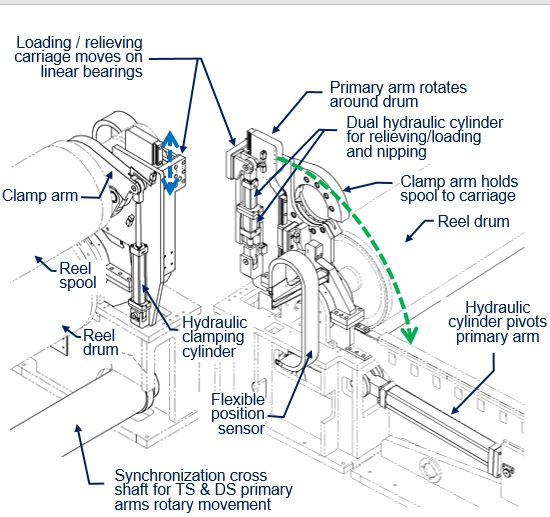
Primary arm assembly of reel with piggybacked hydraulic cylinders for primary arm nipping, relieving and loading
When dual hydraulic cylinders are used to control each primary arm, they are piggybacked end-to-end; the shorter cylinder handles nipping the spool to the drum, and the longer cylinder handles loading and relieving. The movement of this primary arm assembly is controlled as follows:
- The hydraulic clamping cylinders pivot the clamp arms to lock the spool to the carriage.
- The dual hydraulic nipping/relieving/loading cylinders lower the spool onto the drum, relieve the weight of the reel spool, and provide the desired linear nip load between the building roll and the drum.
- The hydraulic turning cylinders and synchronizing cross shaft control the rotation of the primary arms around the drum bearing housings (for example, lowering the building roll to the rails).
- The proximity switches and flexible sensor provide feedback to the control system. This feedback is used to determine if movement is allowed and to continuously adjust the relieving/loading cylinder pressure to maintain the desired nip load throughout the turn-up sequence.
Modern machines also include a primary to secondary arm nip load transfer control by decreasing primary clamping pressure at the same time as increasing the secondary arm loading pressure.
If you are seeing unacceptable bottom waste and would like to speak to someone about incorporating primary arm nip relieving and primary to secondary nip loading transfer, please contact your Valmet representative.