Reading fluids circuit diagrams - hydraulic circuit examples
Jan 2, 2018
The previous article in this series introduced fluids (hydraulic and pneumatic) circuit elements. This article will describe three example hydraulic schematic diagrams.
Hydraulic (oil under pressure) controls are used when very heavy components must be moved with accuracy and speed is not the primary goal. Hydraulics should not be used in systems that must be very clean, such as food manufacturing, due to possible leaks from valves, seals or hoses. Movement is much slower than with pneumatic (gas, usually air, under pressure) control. A hydraulic system uses a reservoir to dump the oil when their direction or state is changed, as opposed to pneumatics which can vent to the machine hall air.
Since hydraulic oil is not compressible, a hydraulic system can smoothly live and move loads requiring great force and the movement is not delayed. Energy-wise, hydraulics are also less costly to operate than pneumatics. Environmentally, hydraulics can leak, however they are quieter than pneumatics when operating.
Case 1: Hydraulic cylinder activation
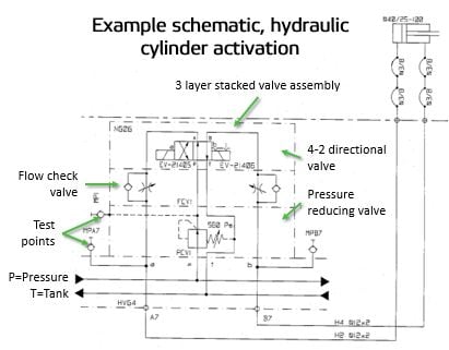
This basic hydraulic circuit of activating one hydraulic cylinder uses a three layer stacked valve assembly. First, it takes system pressure (normally ~2000 psi) and passes it through a pressure reducing valve (set for 560 PSI). In the figure this is the lower dashed rectangle of the three layer valve assembly.

Hydraulic cylinder activation schematic
Pressure reducing valves and pressure relief valves look very similar on circuit diagrams. The way to tell them apart is where the pilot (dashed) line comes from. If it comes from the upstream, high pressure side of the valve, it’s a relief valve. If it gets its signal from the downstream port, it’s a pressure reducing valve. Note that there is a dashed line that comes out of the spring of the pressure reducing valve. A small amount of oil continuously drains back to the tank through this line to prevent pressure from building up on the spring side of the valve.
Next, the oil goes through a sandwich flow control block - this is the middle dashed rectangle of the three layer valve. The speed of the cylinder, both extending and retracting, is set by adjusting these flow control valves. For hydraulic cylinder speed control, the flow controls are orientated to meter out of the cylinder vs. metering in to them. You can tell by the flow control check valve which way the flow is metered. This type of metering provides smoother operation and is less prone to sudden uncontrolled movements under load. Oil flowing into the cylinder is not controlled and bypasses the flow control valve via the internal check valve.
From there, the oil passes through a 4 way – 2 position directional valve, the upper dashed rectangle of the three layer valve assembly. 4-way directional valves have 4 ports (P, T, a, b). 2 position directional valves only have 2 possible positions. Both sides of the directional valve are controlled with solenoid coils, with the "b" side having a detent function. A detent is a shallow groove in the solenoid spool that keeps it from moving in case the "b" coil loses power. It is critical that only one of the solenoid coils be energized at one time, especially for AC voltage coils. If both are energized, the coils will quickly burn out and will need to be replaced. DC coils are more resistant to failure, but will eventually fail too if both are left on. The above directional valve flow path is shown for the "b" coil being energized – oil going to port "a". When the "a" coil is energized and the "b" coil is de-energized, the spool shifts to the other side and allows oil to flow to the opposite port "b".
Case 2: Turning a sizer applicator beam via hydraulics
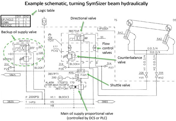
Below is a hydraulic circuit that turns the applicator beam on a SymSizer. Main hydraulic pressure, P is reduced as it goes through proportional valve PCM1 that can be controlled by the DCS or PLC. This pressure is used to load the bottom applicator beam. Another oil supply, PCV1, is used if there is a loss in power according to the logic table. Notice that it is energized all the time, with the oil directed to a plugged port. Only when there is a loss of power to the solenoid does it send oil to the beam cylinders. These two oil sources are connected with a shuttle valve, FVV1. The oil supply with the higher pressure shifts the shuttle valve over and is sent forward to the downstream hydraulic components.

Schematic for hydraulic turning of a sizer applicator beam
Next in the circuit is a counterbalance valve. This valve will not allow oil to exit the rod end of the beam turning cylinders without pressure on the cap end of the cylinders (dotted line). I have also seen pilot operated check valves in this location which essentially does the same thing but is not adjustable like a counterbalance valve is. In either case, the counterbalance valve prevents the beam from loading when there is no hydraulic pressure on the cylinder cap end. Without this type of valve, the unbalanced weight of the applicator beam, which is heavier on the roll side of the turning bearings, will load the beam to the roll when oil pressure is lost. This would be an unsafe condition. When changing counterbalance valves, setting them to the correct pressure should be performed at the factory whenever possible with benchboard calibration equipment.
Next in the circuit are the flow control valves. In hydraulics, flow control valves are almost always oriented to “meter out” of the cylinder. This provides better and smoother movements of the load. Note that this rule does not always work for pneumatic circuits as air is so compressible, oil is not. When controlling overhung loads with pneumatics, both meter in and meter out are often required on the same side of the cylinder. Finally, the oil goes through a 4-2 directional valve which determines whether the beam loads or unloads. Note that in this case, the oil going to and coming back from the cylinders are split in the middle. There is no way to independently adjust the speed of each end of the beam. In this case, the supply and return lines have tees in the center of the machine to equalize flow to both ends as much as possible.
Case 3: Hydraulic reel secondary arm control
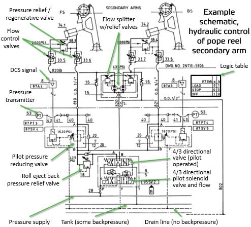
The next graphic shows the hydraulic schematic for a pope reel secondary arm control circuit. The secondary arms are controlled by a 4/3 directional solenoid valve, SV2. Mounted just above the solenoid valve on the drawing are two small flow control valves that can be used to slow down or speed up the shifting of the larger 4/3 directional valve that is mounted just above the flow control valves. In reality, the larger pilot operated directional valve is mounted to the block and the flow control and solenoid valves are mounted on top of larger valve.

Hydraulic reel secondary arm movement schematic
This type of control system uses a low flow device to pilot a high flow device. When the "a" port is energized, oil flow proceeds through flow splitter #15, which provides both cylinders the same amount of oil flow that synchronizes the ejection of the spool to the brake station.
Notice there are relief valves on the downstream side of the flow splitters. These prevent uncontrollable pressure buildups that can occur since flow splitters can actually act as pressure intensifiers under the right conditions. During ejection, backpressure on the rod end of the cylinders is controlled by pressure relief valve #18. This helps control the thrust pressure caused by the weight of the arms and spool at ejection.
The speed of secondary arm movements is controlled with adjustable flow control valves on the cylinders.
When the secondary arms are loaded up to the reel drum, the main directional valve is shifted to supply oil to the rod end of the cylinders. This oil supplies pilot operated pressure reducing valves #7.
Loading pressures are sensed by pressure transmitters and controlled by the DCS or PLC according to a loading curve that is set to control the desired roll structure.
Mounted to the cylinder rod ends are pressure relief valves #38 that are used in case of sudden shocks to the system such as during threading, turnups, or messy sheet breaks. It also acts as a regenerative valve – allowing high rod end pressure to pass back into the cap end during ejection. This reduces the amount of oil flow required from the pump and therefore helps keep the size of the pump smaller than would be required if there were no regeneration.
Note that when SV2 is totally de-energized, there is no flow to either side of the larger directional valve. When this happens, the larger directional valve spool is shifted to its center position, which blocks all 4 ports and so holds the secondary arms in a locked, fail safe position.
Finally, this circuit utilizes a "drain" line connected to SV2. A drain line has no backpressure in it. Flow out of SV2 to the drain line prevents any back pressure from building up that may slow down shifting of the main directional valve. Oil lines to "tank" usually have 15-30 psi of backpressure as they are passed through oil filters before entering the tank.
For more information about reading hydraulic and pneumatic circuit diagrams, read the next article in this series which describes sample pneumatic circuits, or contact your Valmet representative.