Make slitter adjustments safely, provide better paper quality
Nov 10, 2020
This article discusses checks and adjustments that operators need to regularly make for winder slitter positioning systems. While these instructions are for Valmet slitters and the Valmet Slitter Positioning System (WindPosit system), the band/blade gap, side load force, band/blade overlap and cant angle are common factors with all slitter systems.
Read further for step-by-step instructions to safely check and adjust top and bottom slitters, as well as the importance of each adjustment. Additionally, go to Slitter Management to learn more about safe and accurate slitting.
![]()
 |
WARNING: Slitter bands and blades are sharp! Extreme caution should be used when working on or around the slitters and related equipment. Most accidents occur when people are in a hurry and not thinking about what they are doing. For maximum safety, follow these general rules, use common sense, and stay alert:
|
![]()
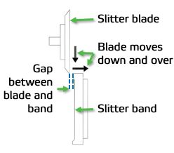
Blade / Band gap adjustment
The band/blade gap is the horizontal distance between the blade and the band before the blade is loaded against the band. An incorrect band/blade gap could result in a poor cut. The correct gap is pre-set at installation.
On the Valmet Slitter Positioning System, the band/blade gap must be reset whenever the blade unit is moved separately from the band unit.
NOTE: The gap between the blade and band must be consistent for all slitters to ensure a constant side-loading force on each slitter.
To check/set the band/blade gap:
- Before checking or adjusting the band/blade gap, make sure that the following conditions are met:
- the winder is at zero speed
- the slitter motors are turned off at the slitter motor overload panel and the control is locked out
- the slitters are engaged and loaded
- Enter the slitter section.
- Disable the loading cylinder (for the individual slitter being adjusted) by closing its air valve (typically black or blue air line). The slitter blade will unload from the band.

If the gap is incorrect, move the blade unit toward/away from the band unit until the appropriate gap is reached. Do this as follows:
- Turn the local Band Locking switch to ON. This will close the transfer rod air connections to the band carriage. It will remain locked to the slitter beam and will not move with the transfer rod.
- Move the blade unit toward/away from the band unit using the respective slitter JOG switch. The band unit will remain in its original place. The respective blade unit will unlock from the slitter beam, and lock to the transfer rod, moving with the transfer rod in the direction it was jogged.
- Release the switch when the desired blade position has been reached. The blade unit will unlock from the transfer rod and relock onto the slitter beam.
- Turn the local Band Locking switch to OFF.
- Enable the loading cylinder (for the individual slitter being adjusted) by opening the valve to its loading cylinder (typically blue or black air line). The slitter blade will load against the band.
- Exit the slitter section.
- After checking that no one is in the slitter area, enable the slitter motors by turning them on at the slitter motor overload panel.
- Resume normal operation.
Measuring and adjusting side load force
The blade makes two movements when positioning for slitting. First, it moves "down" (engages) toward the band, and then it makes a lateral movement (loading) against the band (as shown in the previous figure).
The lateral movement depends on the gap setting between the blade and band. This gap should be set between 0.16" – 0.24" (4 – 6 mm).
Side loading has a significant impact on blade life and cut quality. The loading pressure required to keep the blade in contact with the band depends on the type of material being slit. It is important that the side loading force be set as light as the process will allow:
- The side loading force must be heavy enough to enable the band to drive the blade. However, excessive side loading causes faster blade wear.
- The heavier the basis weight, the more side loading needed. Heavier papers create more lateral force on the blade.

The loading force can be adjusted using a pressure reducing valve. See the engage cylinder flow control knob in the operating and maintenance manual for your Valmet slitter positioning system.
Recommended sideload pressures and forces for Valmet winders are also shown in the table.
| Grade | Pressure (PSI) | Force (lbs) |
|---|---|---|
| Tissue papers | 35 - 41 | 12.8 - 15.1 |
| Printing papers | 41 - 46 | 15.1 - 17.3 |
| Light boards | 46 - 58 | 17.3 - 21.8 |
| Coated boards | 46 - 58 | 17.3 - 21.8 |
| Linerboards | 51 - 61 | 19.1 - 23.2 |
To measure/adjust the side loading force:
- Before measuring or adjusting the side loading force, make sure that the following conditions are met:
- the winder is at zero speed
- the slitter motors are turned off at the slitter motor overload panel and the control is locked out
- the slitters are engaged and loaded
- To measure the current side loading force, push a hand-held force gauge against the center of the knife holder until the blade just comes away from the band. Record the gauge reading.
- To adjust the side loading force, increase or decrease the pressure regulator for slitter loading. NOTE: There are typically two or three regulators: one for all intermediate slitters, and (depending on the design) either per trim slitter, or one for both trim slitters.
Blade / Band overlap (depth) adjustment
The band/blade overlap is the amount that the slitter blade overlaps the slitter band when engaged.
- Too little overlap can cause the blade to ride up onto the band, instantly dulling the blade, and possibly not even cutting the web.
- Too much overlap can dull blades prematurely and cause the web to be fractured or folded.

The diameters of re-ground blades and bands change, affecting the amount of overlap. If required, the position of the blade can be adjusted.
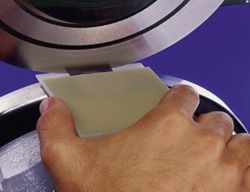
A chord gauge, typically supplied with the slitters, is used to measure the correct depth of overlap for the intended product. If you do not have a chord gauge, contact your Valmet representative for one.
The recommended overlap for various grades of paper is shown in the table.
| Paper Grade | Overlap | Chord Length | |||
| 5/8" | 3/4" | 7/8" | 1" | ||
| Tissue papers | < .030" | ||||
| Printing papers | < .030 - .050" | ||||
| Light boards | .050 - .060" | ||||
| Coated boards | .050 - .060" | ||||
| Boards, liner papers | .060 - .080" | ||||
To adjust the depth of the slitter blade:
- Before measuring or adjusting the band/blade overlap, make sure that the following conditions are met:
- the winder is at zero speed
- he slitter motors are turned off at the slitter motor overload panel and the control is locked out
- the slitters are engaged and loaded
- Place and hold the gauge on the top of the band.
- Loosen both blade holder locking handles to unlock the blade holder from the blade carriage.
- Turn the depth adjustment knob to move the blade holder toward or away from the band until two points on the curve of the blade rest on the two adjustment points of the chord gauge (as shown in figure).
- Tighten the blade holder locking handles to lock the position of the blade holder on the blade carriage.
- Exit the slitter section.
- After checking that no one is in the slitter area, enable the slitter motors by turning them on at the slitter motor overload panel.
- Resume normal operation.
Cant (shear) angle
The cant, or shear, angle is the angular relationship between the band and the blade. The appropriate cant angle has been premachined into Valmet slitter holders. Newer slitters are designed with a 0.1° - 0.25° cant angle. Older slitters were as much as .05°. The maximum cant angle should never exceed .05°. The best cant angle for a specific product is the minimum angle required to reliably slit the web.
Debris can occasionally work its way between the blade holder and the blade carriage assembly, especially after adjusting the blade depth. This debris can affect the cant angle. If blades are prematurely wearing, or the cut does not look right, and the band/blade gap and the blade depth have already been checked out, the problem may be the cant angle.
If the cant angle is incorrect, maintenance personnel should assess and correct the problem. Possible solutions include:
- cleaning out any debris
- shimming under the blade holder
- replacing the blade holder
To measure the cant angle:
- Before measuring or adjusting the cant angle, make sure that the following conditions are met:
- the winder is at zero speed
- the slitter motors are disabled inside the slitter motor overload panel and the panel is locked out
- the slitters are engaged and loaded
- Place a feeler gauge between the blade and the band, behind the cut point, to measure the gap. Refer to the following figure and table for correct placement of the gauge and recommended cant angles. The gap is relative to the chord length: the longer the chord, the greater the gap. NOTE: It is very important to always have a positive cant angle.

Measuring the cant (shear) angle
| Cant Angle | Chord Length | |||
| 5/8" | 3/4" | 7/8" | 1" | |
| Measured Gap | ||||
| 0.1° | .0011" | .0014" | .0015" | .0015" |
| 0.2° | .0023" | .0027" | .0031" | .0035" |
| 0.3° | .0031" | .0039" | .0047" | .0051" |
| 0.4° | .0043" | .0051" | .0059" | .0067" |
| 0.5° | .0055" | .0067" | .0075" | .0087" |
Blade cant (shear) angle relative to measured gap
Refer to the OEM instructions that came with your slitter system operating and maintenance manual for the safe operation of your slitter system.
Contact your Valmet representative for information about Valmet's Slitter Management program which addresses operator safety and training.


