Comparison of hard and soft bearing roll balancing methods
May 17, 2022
Safety during roll balancing
The following are general safety precautions when balancing rolls:
- Use care when working around open belt balance machine drive systems.
- Always use a guard to surround the area of a roll with trial weights temporarily fastened during rotating operations.
- Use bearings in good condition with proper speed and load ratings when balancing rolls.
Hard bearing balance method
Hard bearing type balancers measure residual unbalance. This is the force of a measured quantity in a known direction attributed to uneven centrifugal force caused by unbalance. Vibration sensing devices on the balance machine measure and plot the force while the roll is rotating.
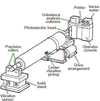
Layout of roll balance machine for hard bearing balancing
The general method used to balance a roll on a hard bearing balancer is as follows:
- Place the roll to be balanced on the machine rollers directly on the bearing mounting surfaces.
- The roll size, speed and distance from bearing surface to planes where weight will be added or subtracted and distance between the added weights must be keyed into the balance machine control panel.
- A mark on the roll journal and a photoelectric head is used to orient the machine for establishing the vector of the unbalance.
- The units of unbalance measure are selected to establish how much unbalance is represented by each unit on the vectormeter.
- Make sure that there is no drive belt slippage, as phase angle is lost when slippage occurs.
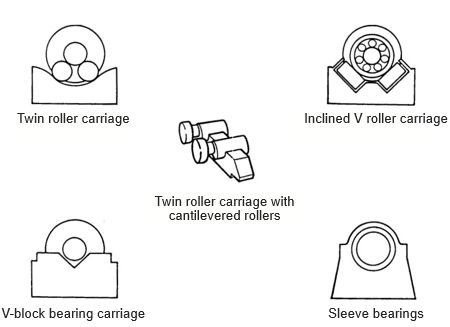
Roller supports
Drive belt pulley and support roller diameters can affect unbalance readings if sized incorrectly for the roll diameter being balanced. It is recommended that the frequency between the roll being balanced and the rotating components of the machine be greater than 60 RPM.
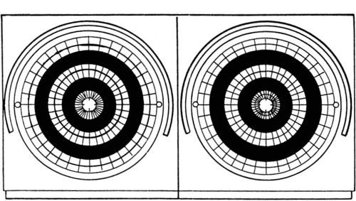
Vectormeter display
As the roll is rotated, a dot of light appears on the vectormeter showing the magnitude of the unbalance by the number of units it is away from the center and the phase by the angle from the phase mark.
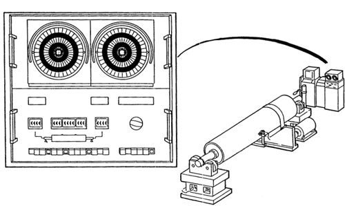
Machine controls
Instrumentation and software can be supplied with the balance machines to calculate the amount and location of counterweight needed to reduce the amount of residual unbalance to acceptable limits. Once the amount and location of counterbalance is determined, weight is removed or installed to reduce the unbalance to specified amounts and a final check is made.
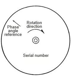
Roll markings
All rolls built and balanced by Valmet after 1986 are marked with a serial number, phase angle reference mark and rotation direction stamp. Any subsequent balancing should use the same phase angle and rotation. The importance of phase angle and rotation direction when check balancing rolls is to help determine what changes may have caused unbalance. The original documentation can be compared with current data.
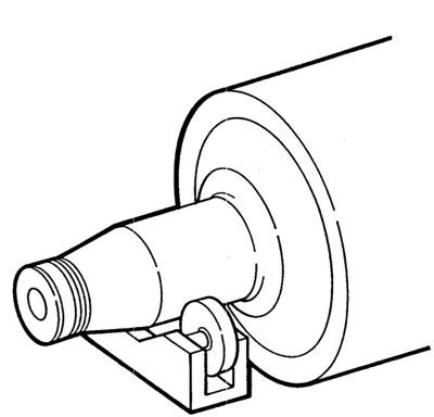
Press roll running on flinger fit
Rolls with tapered bearing fits cannot be supported on the tapers with balance machine rollers. The straight fit above the taper can be used to balance the roll on if it is concentric with the bearing fit. Effort should be made to maintain the journal fits used for balancing rolls with tapered bearing fits. Journal surfaces which have been metal sprayed or sleeved should not be used on hard rollers.
Soft bearing balance method
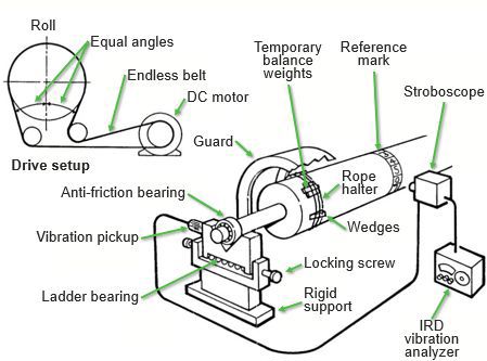
Layout of roll balance machine for soft bearing balancing
Soft bearing type balancers use a stroboscope and vibration pickups to measure vibration amplitude and direction. The amount of unbalance is measured by movement on ladder bearings, usually in .001 inch. Old style machines measure dynamic runout rather than residual unbalance.
- The roll to be balanced with anti-friction bearings installed is placed on stands with ladder bearings which allow each end of the roll to oscillate.
- The drive belt around the roll should be of equal angles on the incoming and off going sides of the roll to allow uniform movement of the roll on the ladder bearings.
- The amount the roll oscillates while rotating is a function of the amount of unbalance. Vibration pick ups monitor the horizontal movement vibrations.
- A stroboscope is directed at a vector chart at the end of the roll or at a numbered band around the center and fires at the peak of each cycle, giving the operator the phase of the unbalance.
- The vibration analyzer measures the vibration level, giving the operator an idea of the amount of unbalance.
- Trial weights are temporarily fastened to the outside of the roll body and the procedure is repeated.
The end result is that trial weights are placed in the correct amounts and locations to reduce the amount of movement of the roll on the ladder bearings to acceptable dynamic runout levels, referred to as free bearing amplitude. Permanent weights are made and installed on or in the roll and a final vibration level check is made.
Rolls should be balanced whenever possible on journals to avoid variables introduced by bearing runout.
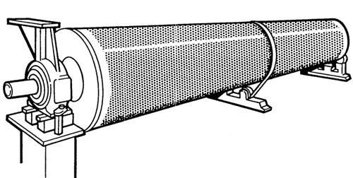
Suction roll being balanced
Many IRD-style balance machines are not equipped to run rolls on rollers and anti-friction bearings are used. Some rolls are designed in such a way that they cannot be supported on rollers.
For assistance with roll balancing, contact your Valmet representative.