Reading fluids circuit diagrams - pneumatic circuit examples
Jan 9, 2018
The previous articles in this series introduced fluids (hydraulic and pneumatic) circuit elements and described three example hydraulic schematic diagrams. This article will describe two example pneumatic systems. In each case, the equipment being moved is relatively light weight and does not have to move with exceptional accuracy, so pneumatic control is appropriate.
Pneumatic Case 1: Lowering cradle hold stops
The lowering cradle of a winder receives the discharged set of rolls from the roll ejector, and then pivots to roll hold position and then lowers them to the mill floor (discharge position). Position sensors are provided to detect roll in cradle, cradle is raised, waiting / roll hold position and cradle is down / discharge position.
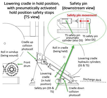
Lowering cradle with hold position safety pins
The lowering cradle includes a pair of "roll hold" position mechanical stops to prevent the cradle from lowering to the floor (with a wound roll) in event of a hydraulic or mechanical cylinder failure. The cradle roll hold stops (safety pins) are designed to hold the lowering cradle at intermediate (hold) position before discharging the rolls to the floor.
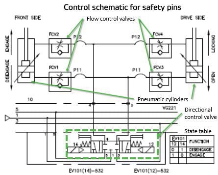
Safety pin pneumatic control schematic
When coil 12 of pneumatic directional control valve EV101-532 is energized, the pneumatic cylinders extend preventing the cradle from lowering. When coil 14 of valve EV101-532 is energized, the cylinders retract allowing the cradle to lower.
Speed of the cylinders movement is controlled by pneumatic flow control valves FCV1 and FCV2 (TS stop) and FCV3 and FCV4 (DS stop).
Pneumatic Case 2: Belt threader for lead-in roll
A belt threader mounted above the lead-in roll on a winder has two threading belt frames and two sets of pneumatic positioning cylinders. The belted threader has three positions: home (belts away from roll), first threading position (both belts touching lead-in roll), and third position (only second belt touching lead-in roll).
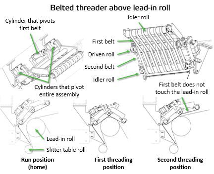
Belted threader with two belts, above winder lead-in roll
Both belts are driven by a common driven roll and each belt also has an idler roll. During normal running the belted threader is in the home position. At the beginning of threading, both belts touch the lead-in roll and the tail is fed into the first (first belt) nip and passes into the next (second belt) nip. After the tail is successfully threaded past the lead-in roll, the threader moves into the second threading position and the first belt raises from the lead-in roll. When threading is complete, the belted threader moves back to the home position.
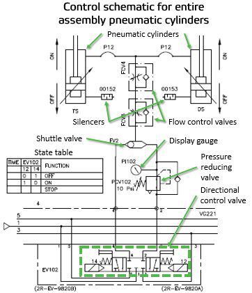
Control schematic of cylinders that pivot the entire belt threader assembly
Two cylinders move the entire assembly toward/away from the web. Movement is controlled using a 5/3 directional control valve. The threading assembly will rise by energizing EV102, coil14, to allow full pressure into the cylinder rod end. The assembly is lowered by energizing coil 12 to allow low pressure into the rod side of the cylinder. This pressure is set using pressure reducing valve PCV102 to almost relieve the weight of the frame assembly but not high enough to lift it (~10 psi). The pressure is displayed on gauge PI102. Speed is controlled with in-line flow controls FCV3 & FCV4, one-way restrictor valves.
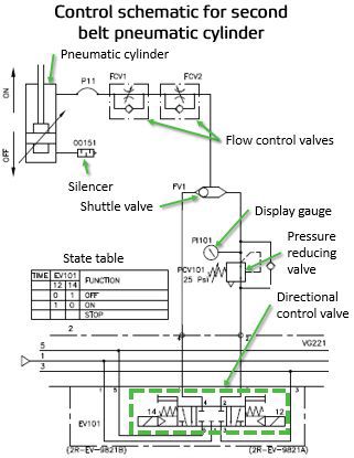
Control schematic of cylinder that pivots the first belt
A third cylinder moves the first belt frame toward/away from the web, allowing it to lift away from the web while the second belt frame remains near the web. Movement is controlled using 5/3 directional control valve EV101.
Nip load is controlled using a pressure regulator. Pressure should be set using pressure reducing valve PCV101 to allow the paper to proceed forward smoothly, while still allowing the paper to be pulled out of the threading nip without tearing it (~25 psi). Pressure is displayed on gauge PI101. Speed is controlled with one-way restrictor valves FCV1 & FCV2.
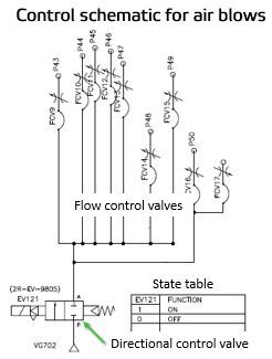
Control schematic of air blows
Air blows help to guide the threading tail through the winder during threading sequences. One set, called "threading" air blows, guide the tail onto and along various threading pans from the unwind to the rear drum. This group of air blows is used only during threading. The air blow design (knives, jets, nozzles, perforated pipes and sequencing) and volume of air can vary, but in this example, all threading air blows are controlled on/off at the same time, with a single 2/2 directional control valve EV121. The volume of air flow can be adjusted using a needle valve (FCV9 through FCV17) located near each air blow.
For more information about reading hydraulic and pneumatic circuit diagrams, read the previous articles in this series, or contact your Valmet representative.