Start with an audit - common reeling problems and their solutions
Aug 3, 2016

Depending on the reeling challenge being faced, Valmet has several service options that can be tailored to suit the individual and custom needs of any given mill. Valmet experts have many years of experience in the industry that will be utilized, with each case unique and specific to the needs of the given challenge being faced.
Start with an audit
Valmet offers reel audits and assessments which help to fully understand all aspects of the challenge or issue, not only the obvious ones:
- Process Studies
- Mechanical condition inspection
- Control and operation assessment
- Risk and safety assessments (any operator and machine interaction has a potential safety risk)
Common reeling problems and their solutions
There are multiple reasons for any given reeling issue or challenge. Discussed here are some common items found when Valmet assesses reel operational challenges.
Problem: Wrinkles are seen throughout the jumbo roll.
Often, older reels have a secondary arm synchronizing shaft which utilizes a fixed-link shaft or tube across the machine to keep both secondary arms moving in synchronization with each other. In many cases, this can cause operational issues when the tending and drive side loading rollers on these arms are not perfectly aligned with each other. This can be due to mechanical wear, control or cylinder malfunctions, or paper related issues causing jumbo roll diameters to differ front to back on the reel.
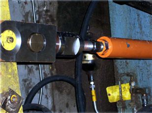
Figure 1 - Example application of slotted linkage design, with integrated wear components.
Solution: Valmet has designed a cross-shaft linkage concept (Figure 1) which allows a small amount of float or free-play in the system. This design accommodates mis-alignment of the loading rollers on the secondary arms. This small upgrade opens the operating window on the reel and tolerates deviations within the loading system. This must be engineered to fit on any given reel, but is an easy solution to adapt to virtually all types of reels.
Problem: Jumbo rolls bounce or vibrate consistently on the reel.
It is not uncommon to see a jumbo roll bouncing or vibrating on a reel. This occurs on both new and old reels of all design types. The source of bouncing can be from any number of sources. It is often exaggerated by looseness or freeness in the mechanical system of the reel itself.
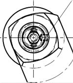
Figure 2 - Secondary arm loading roller on a reel.
Solution: One way to "dampen" the ability of the jumbo roll to bounce on the reel is to provide a small amount of rolling resistance or friction to the system. Valmet has engineered a solution that can be adapted to most reels currently in operation. We can redesign the loading rollers on a given reel to be a "locked" position design, which will then slide on the rolling surface of the reel spool bearing housings as the jumbo roll builds on the reeling rails. This new roller (Figure 2) is made of a bronze-type material and has the ability to be indexed to provide maximum longevity to the wear component.
Problem: Primary arm assemblies are damaged due to faulty operation.
There are many instances where a primary arm and its related components are damaged from misuse or faulty operation. The possible sources of the damage are numerous, but there are a few common issues that arise over the life of the primary arms.
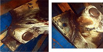
Figure 3 - Examples of damaged bearing housings resulting from over-driven primary arms.
Many older reels raise and lower the primary arms through the use of a cross-shaft assembly. This is often driven by an electric motor. The electric motor is turned off in the fully raised and lowered positions by limit or proximity switches on some reels. If these switches become displaced or are faulty, the primary arms can be over-driven. This may result in component damage (Figure 3) and an unsafe condition at the mill site.
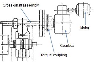
Figure 4 - Example of an old design torque coupling arrangement
The systems are usually designed with a mechanical fail-safe, such as a torque coupling. Over the years, these couplings become an operational and maintenance item, which is often overlooked. With old designs, these couplings are installed between the gearbox and the cross shaft assembly (Figure 4). Setup of the torque coupling in these designs can be difficult, as they need to be set tight enough to lower a reel spool with paper, but not too tight to prevent mechanical damage to the reel if the arms are over-driven. If the coupling is set too loose, the primary arms can free-fall to the rails. As a result, most torque couplings with this design are set too tight, which then does not protect the equipment from damage and can create an unsafe operation on the machine.
Solution: These old systems can be engineered to relocate the torque coupling before the gearbox. Not only does this provide a safer operation and ease of maintenance, it also allows for a much smaller and less expensive coupling to be used.
Problem: Reel loading pressures are at or approaching maximum system pressures.
It is quite common to see an old reel running with high system pressures to provide the required loading on the machine. When you see this, it is a sign that something may be at, near or beyond the capacity of the given reel. The most common reason for this is that operators are now running larger parent rolls than the reel was originally designed for. To achieve the desired parent roll structure loading pressures must be increased to compensate for mechanical and loading system design shortcomings.
Running with very high loading pressures can not only cause damage to equipment, it may also be an indication that you are approaching or have exceeded critical design limits of the machinery. This results in any number of failures, including unexpected roll kick-outs, reel spool failures and machine component breakage.
Solution: A Valmet reel audit can determine which components are operating beyond their design specifications, and modifications in the process or equipment may be recommended.
Problem: Jumbo rolls are "walking" down the rails.
It is common to see jumbo rolls "crab-walking", as it is often called, down the rails once ejected from the reel. This is usually a sign that something is not correct with the setup or alignment of the machine. When this happens, it not only damages equipment such as the rails and reel spools, it also requires operator intervention to free up the jumbo roll if it becomes jammed on the rails. This is an unsafe interaction.
There are two common causes for this. The first is a mechanical alignment issue, where the critical dimensions and clearances between the reel spools and the rails are no longer being maintained. The other common issue is that the spool housings and rails are of a mismatched or old design (Figure 5, right). This allows too much free play in the system and allows the reel spools too much room to skew front/back on the machine.
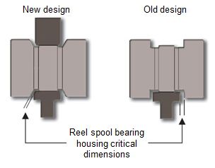
Figure 5 - Reel spool bearing housing and rails relationship. Sometimes you find a mix of both designs, also not good.
Solution: Upgrade to a new beveled design of reel spool housing and rails (Figure 5, left) and/or otherwise address the clearances between spools and rails.
Problem: Wrinkles are apparent when building in the primary arms.
Roll wrinkles and rope marks are quite common on many types of reels and different paper, board and tissue grades. There are some common causes when we specifically speak about board grades, or machines utilizing tape-type turn-up systems.
Very often you may see wrinkles and roping following a turn-up utilizing a tape-style turn-up system. The underlying reason for this is usually due an issue inherent in the turn-up method design. When a tape-style turn-up is used on any machine, the tape usually enters the nip on the drive side. Once it enters the nip, it is immediately wrapped up and around the new reel spool. When that happens, the tape or ribbon, which extends across the machine under the web of paper will be pulled across the machine, tearing the sheet and pulling it up onto the reel spool. By the time the tape and sheet propagates all the way across the machine, there are multiple wraps of paper on the drive side of the machine. This creates a difference in roll diameters. If the tape or ribbon does not cause marking or wrinkles, the usual cause is the diameter difference. You basically have two diameters on a common shaft, both wanting to run at the same surface speed as the reel drum and sheet of paper. The only way for the diameters to equalize is to wrinkle until equal roll diameters are present front and back on the reel.
Solution: There is no quick fix for this design flaw. Valmet currently uses a different method of turn-up for nearly all grades of paper. This method utilizes high-pressure water jets to cut the sheet, from the center of the machine outward to the edges. This method gives a very clean and even roll bottom, as well as equal roll diameters front to back on the reel initially following the turn-up.
For more information on avoiding and/or solving reeling problems, contact your Valmet representative.